Mold for optical component

a technology for optical components and molds, which is applied in the field of molds, can solve the problems of accelerating mold deterioration, affecting and affecting the quality of molds, so as to shorten the life cycle of molds and accelerate mold deterioration. , the effect of shortening the mold li

Active Publication Date: 2007-09-13
FUJIFILM CORP +1
View PDF2 Cites 12 Cited by
  • Summary
  • Abstract
  • Description
  • Claims
  • Application Information

AI Technical Summary

Benefits of technology

[0008]However, according to the conventional mold for the optical lens described above, after the mold is closed, when the mold is opened in order that the molded optical lens is taken out, it is required to pull out from the cylindrically arranged rolling objects either one of the upper mold or the lower mold which is supported by the rolling objects. Therefore, when the mo

Problems solved by technology

Therefore, when the mold for the optical lens is repeatedly closed and opened, the upper mold and the lower mold hit hard each other every time when the upper mold or the lower mold is put back to th

Method used


Image

  • Mold for optical component
  • Mold for optical component
  • Mold for optical component

Examples


Embodiment Construction

[0030]Here will be described embodiments of the present invention, referring to the accompanying drawings as needed.

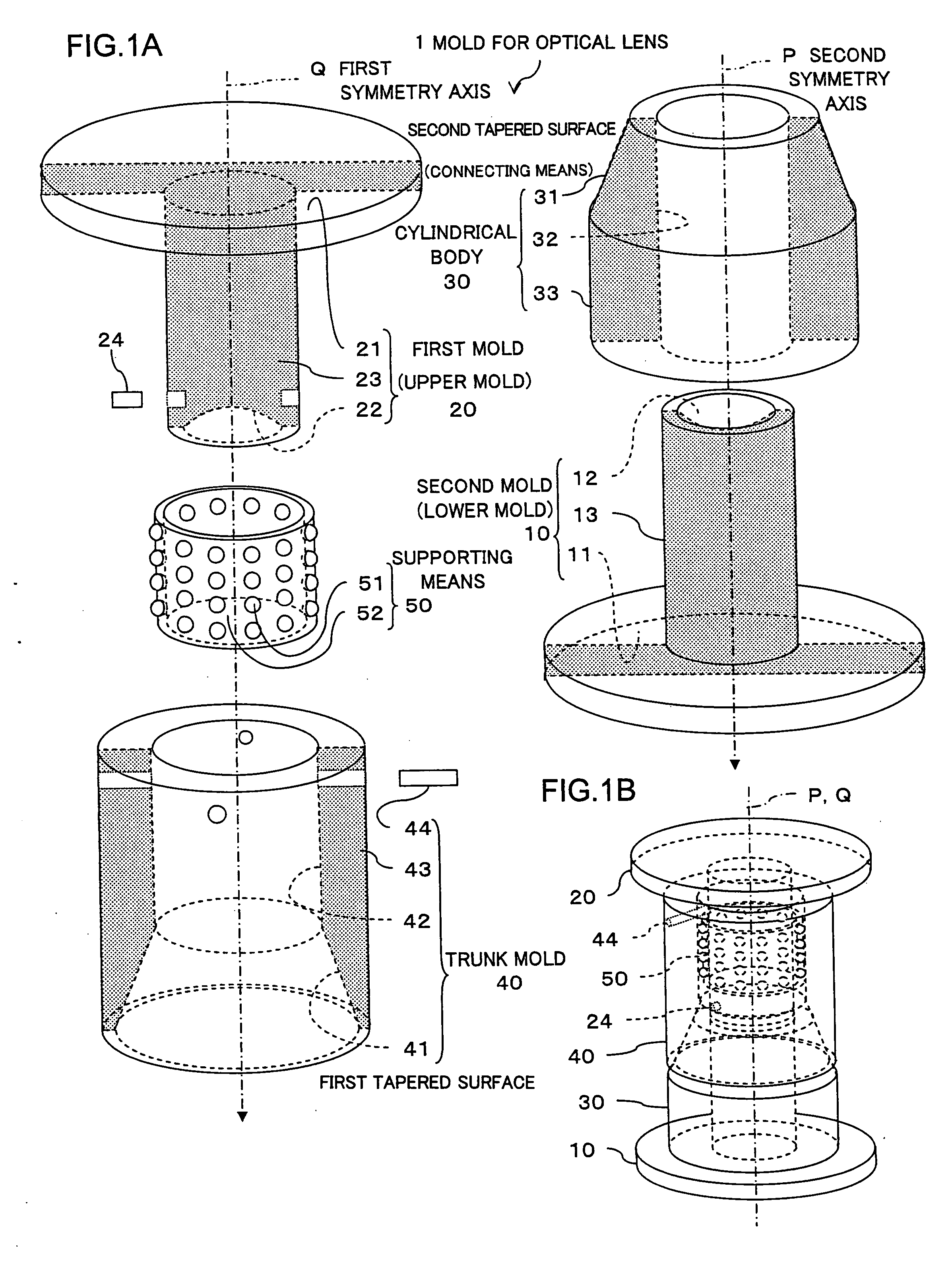
[0031]Referring to FIGS. 1A and 1B, there will be described a mold for an optical lens (an optical component) according to an embodiment of the present invention.

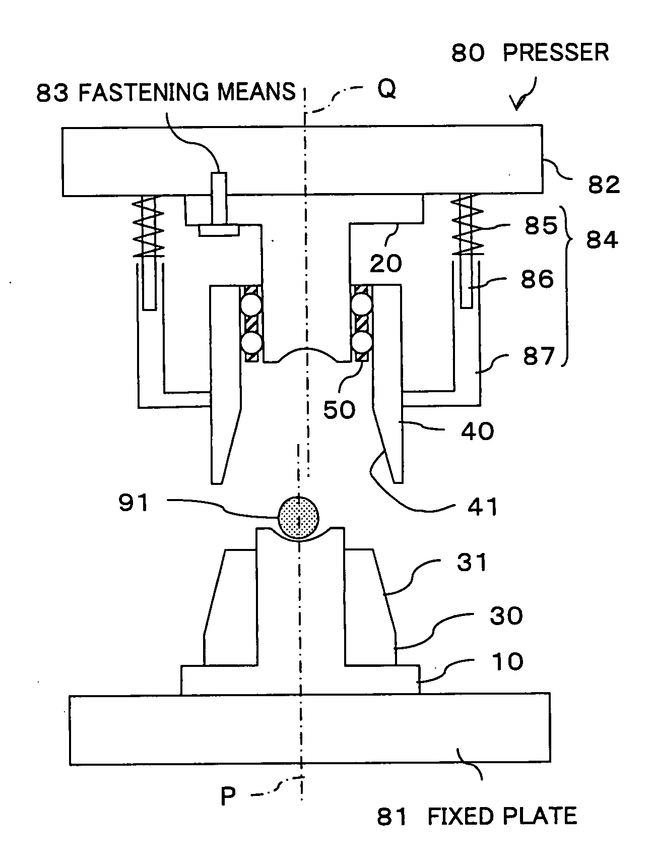
[0032]As shown in an exploded perspective view in FIG. 1A and an assembly drawing in FIG. 1B, the mold 1 for the optical lens according to the embodiment includes a lower mold 10 (a second mold), an upper mold 20 (a first mold), a cylindrical body 30, a trunk mold 40, and a supporting means 50.

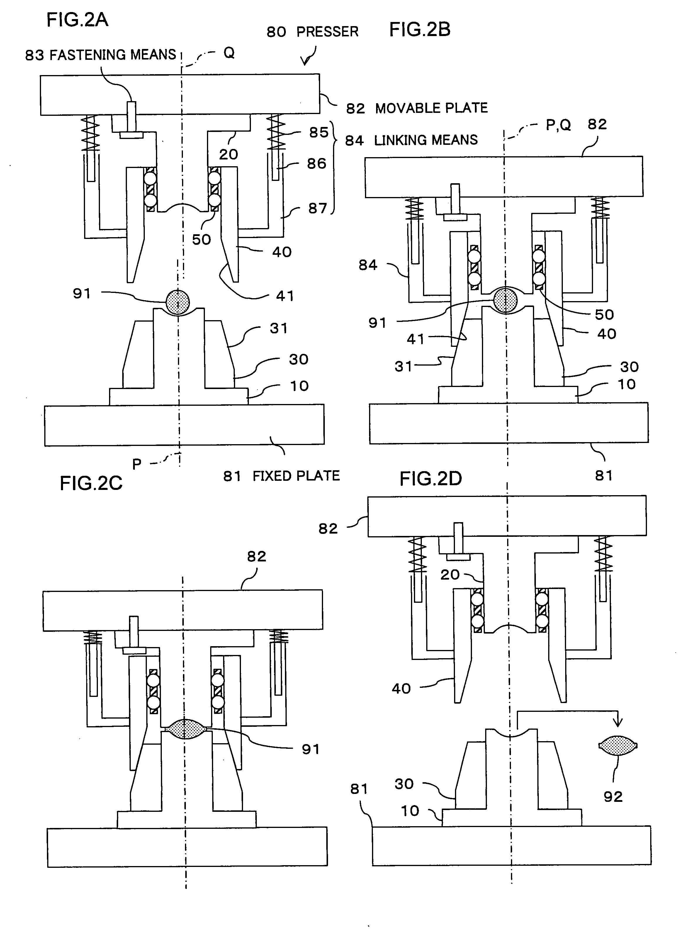
[0033]In the mold 1 for the optical lens with such a structure, a heat-softened lens material (not shown) is pressed with the lower mold 10 and the upper mold 20 to be molded into an optical lens 92 (See FIG. 2D). As shown in FIG. 1B, the mold 1 for the optical lens can align a second symmetry axis P of the lower mold 10 with a first symmetry axis Q of the upper mold 20 and then perform pressing. Therefore, the mold 1 ca...


PUM


Abstract

A mold for an optical component is provided which includes a first mold and a second mold which mold the optical component, a cylindrical body whose rotational symmetry axis is identical with a second symmetry axis about which a second mold is rotationally symmetric, a trunk mold whose rotational symmetry axis is identical with a first symmetry axis about which a first mold is rotationally symmetric, a supporting means which supports the first mold in such a way that the first mold moves relatively to the trunk mold in parallel with the first symmetry axis, and a second tapered surface and a first tapered surface which contacts the second tapered surface, which connect the cylindrical body with the trunk mold in such a way that the second symmetry axis is identical with the first symmetry axis.

Description

CROSS REFERENCE TO RELATED APPLICATIONS[0001]This application claims the foreign priority benefit under Title 35, United States Code, §119(a)-(d) of Japanese Patent Application No. 2006-064756, filed on Mar. 9, 2006 in the Japan Patent Office, the disclosure of which is herein incorporated by reference in its entirety.BACKGROUND OF THE INVENTION[0002]1. Field of the Invention[0003]The present invention relates to a technical field of pressing heat-softened material to mold an optical component using a mold divided into a first mold (an upper mold) and a second mold (a lower mold) which face each other, more specifically, a mold for an optical component to achieve a molding process with high accuracy.[0004]2. Description of the Related Art[0005]In recent years, a highly accurate molding process is required for an optical lens (an optical component) with advanced functions has been developed. Therefore, studies of molding techniques are promoted to meet the requirement. In particular,...

Claims


Application Information

Patent Timeline
IPC IPC(8): B29C43/02
CPCB29C33/303B29C43/021B29C43/36B29C2043/3602B29C2043/3618B29D11/00009C03B2215/72B29L2011/0016C03B11/08C03B2215/49C03B2215/60C03B2215/69B29D11/005Y10S425/808
Inventor SAEKI, TATSUHIKOUTSUGI, MASANORI
Owner FUJIFILM CORP
Why Eureka
Try Eureka