
System for improving cardiac function

a technology of cardiac function and system, applied in the field of cardiac function improvement, can solve the problems of reducing the effectiveness of the heart, back-up of pressure in the vascular system behind the ventricle, and millions of hospital visits internationally, and achieve the effect of improving cardiac function

Inactive Publication Date: 2007-09-13
EDWARDS LIFESCIENCES CORP
View PDF99 Cites 134 Cited by
  • Summary
  • Abstract
  • Description
  • Claims
  • Application Information

AI Technical Summary

Benefits of technology

[0025] The elongate manipulator and the frame may be insertable into the heart simultaneously and the frame may be shaped such that exposure of the distal section of the frame from the distal end of the tubular passage allows the frame to partially expand and exposure of the proximal section of the frame from the distal end of the tubular passage allows the frame to expand to a large cross-section, said expansion causing the passive anchors to penetrate the myocardium to secure the frame to the myocardium.

Problems solved by technology

Congestive heart failure annually leads to millions of hospital visits internationally.
In certain pathological conditions, the ventricles of the heart become ineffective in pumping the blood, causing a back-up of pressure in the vascular system behind the ventricle.
The reduced effectiveness of the heart is usually due an enlargement of the heart.
A myocardial ischemia may, for example, cause a portion of a myocardium of the heart to lose its ability to contract.
Once this tissue dies it no longer functions as a muscle and cannot contribute to the pumping action of the heart.
As this situation worsens, the local area of compromised myocardium may in fact bulge out as the heart contracts, further decreasing the heart's ability to move blood forward.
As the heart begins to fail, distilling pressures increase, which stretches the ventricular chamber prior to contraction and greatly increases the pressure in the heart.
This vicious cycle of cardiac failure results in the symptoms of congestive heart failure, such as shortness of breath on exertion, edema in the periphery, nocturnal dypsnia (a characteristic shortness of breath that occurs at night after going to bed), waking, and fatigue, to name a few.
The stress increase requires a larger amount of oxygen supply, which can result in exhaustion of the myocardium leading to reduced cardiac output of the heart.

Method used


Image

  • System for improving cardiac function
  • System for improving cardiac function
  • System for improving cardiac function

Examples


Embodiment Construction

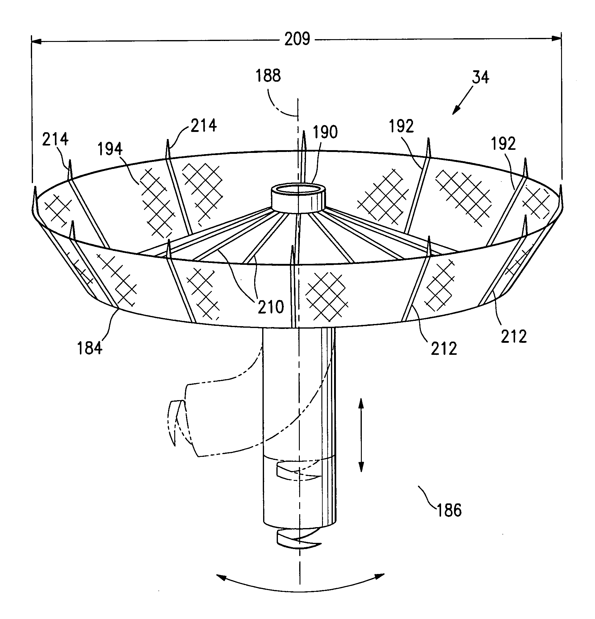
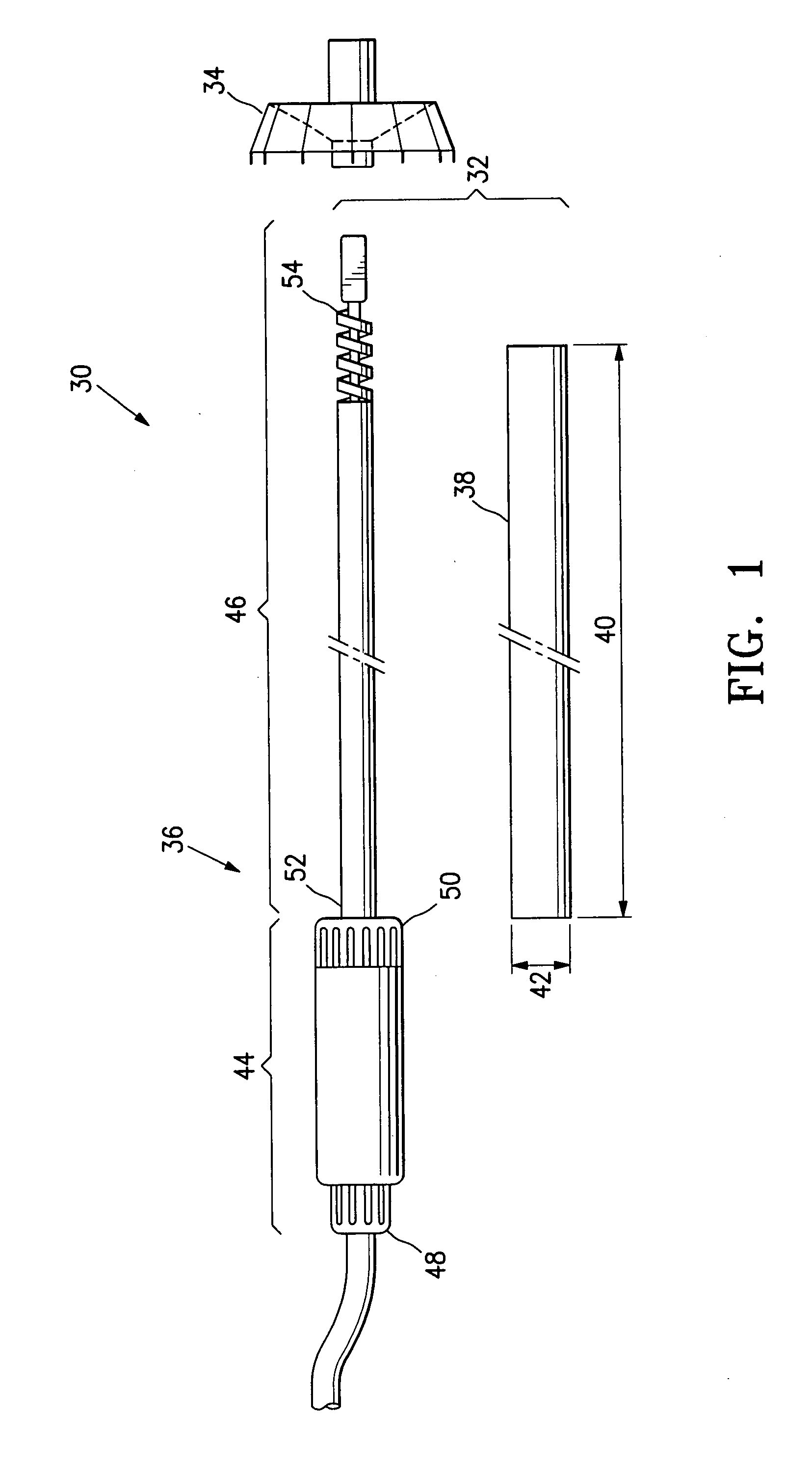
[0125]FIG. 1 illustrates a system 30 for improving cardiac function according to one embodiment of the invention. The system 30 includes a deployment system 32 and a cardiac device 34. The deployment system 32 includes a deployment mechanism 36 and a catheter tube 38.

[0126] The catheter tube 38 is cylindrical with a length 40 of 110 cm and a diameter 42 of 5 mm. The catheter tube 38 has a circular cross-section and is made of a soft, flexible material.

[0127] The deployment mechanism 36 includes a handle 44 and a deployment member 46. The handle 44 has a proximal end 48 and a distal end 50. The deployment member 46 has a proximal end 52 and a distal end 54. The proximal end 52 of the deployment member 46 is secured to the distal end 50 of the handle 44.

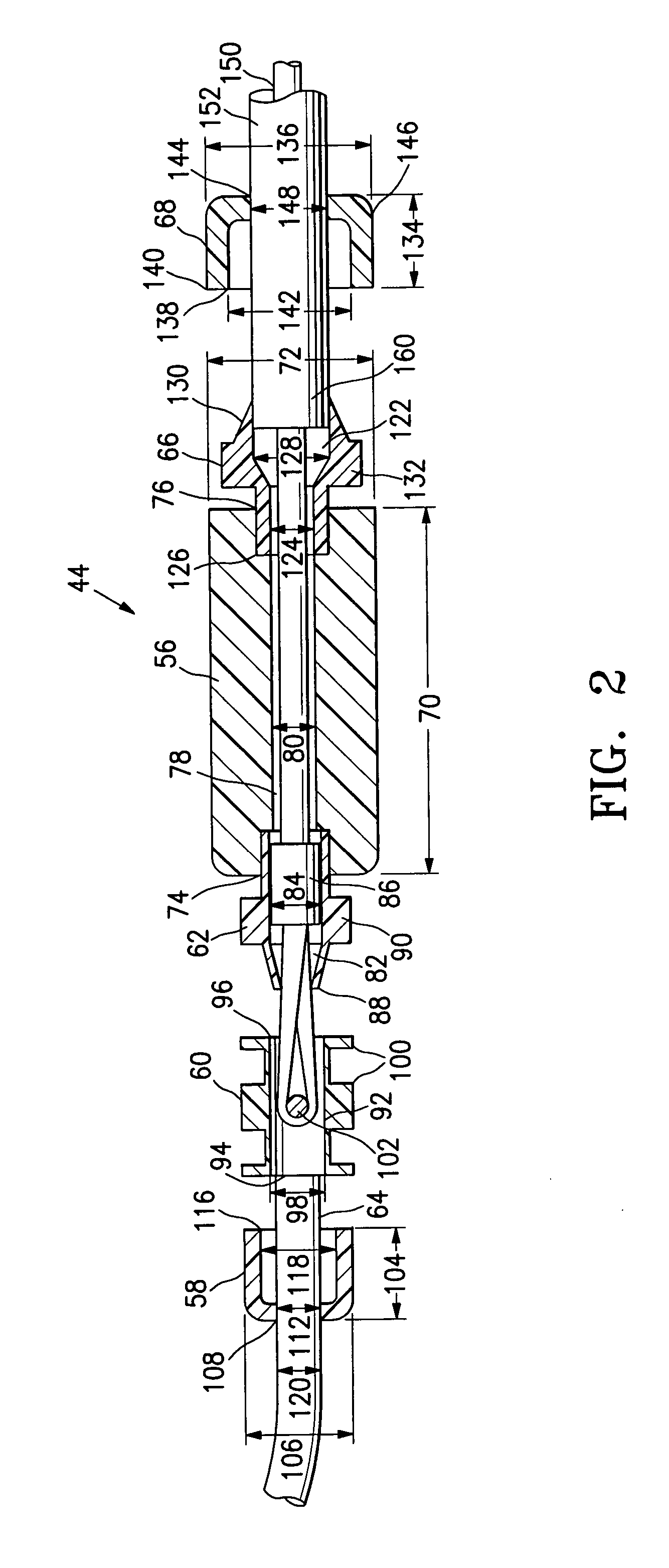
[0128]FIGS. 2, 3A, 3B, and 3C illustrate the deployment mechanism 36 in more detail. FIG. 2 illustrates the handle 44 while FIGS. 3A, 3B, and 3C illustrate components at the distal end 54 of the deployment member 46. The components ...


PUM


Abstract

A system for improving cardiac function is provided. A foldable and expandable frame having at least one anchoring formation is attached to an elongate manipulator and placed in a catheter tube while folded. The tube is inserted into a left ventricle of a heart where the frame is ejected from the tube and expands in the left ventricle. Movements of the elongate manipulator cause the anchor to penetrate the heart muscle and the elongate manipulator to release the frame. The installed frame minimizes the effects of an akinetic portion of the heart forming an aneurysmic bulge.

Description

CROSS REFERENCE TO RELATED APPLICATIONS [0001] This is a continuation of pending U.S. patent application Ser. No. 10 / 436,959 filed on May 12, 2003 which is a continuation-in-part of abandoned U.S. patent application Ser. No. 09 / 635,511, filed on Aug. 9, 2000, which claims priority from expired U.S. provisional patent application Ser. No. 60 / 147,894 filed on Aug. 9, 1999, and are incorporated herein by reference in their entirety.BACKGROUND OF THE INVENTION [0002] 1. Field of the Invention [0003] Embodiments of this invention relate to a method and device for improving cardiac function. [0004] 2. Discussion of Related Art [0005] Congestive heart failure annually leads to millions of hospital visits internationally. Congestive heart failure is the description given to a myriad of symptoms that can be the result of the heart's inability to meet the body's demand for blood flow. In certain pathological conditions, the ventricles of the heart become ineffective in pumping the blood, caus...

Claims


Application Information

Patent Timeline
Patent Type & Authority Applications(United States)
IPC IPC(8): A61M1/10A61B17/00A61B17/12
CPCA61B17/0057A61B17/12022A61B17/12122A61B17/12172A61B2017/00243A61B2017/00575A61B2017/12095A61B2017/00592A61B2017/00597A61B2017/00615A61B2017/00632A61B2017/00867A61B2017/0649A61B2017/00579A61B2017/00663
Inventor KHAIRKHAHAN, ALEXANDERSHARKEY, HUGH R.NIKOLIC, SERJAN D.
Owner EDWARDS LIFESCIENCES CORP
Learn More