

Delay unit for door with a door closer, door closer with a delay unit, and door with a door closer having a delay unit
- Summary
- Abstract
- Description
- Claims
- Application Information
AI Technical Summary
Benefits of technology
Problems solved by technology
Method used
Image

Examples
first embodiment
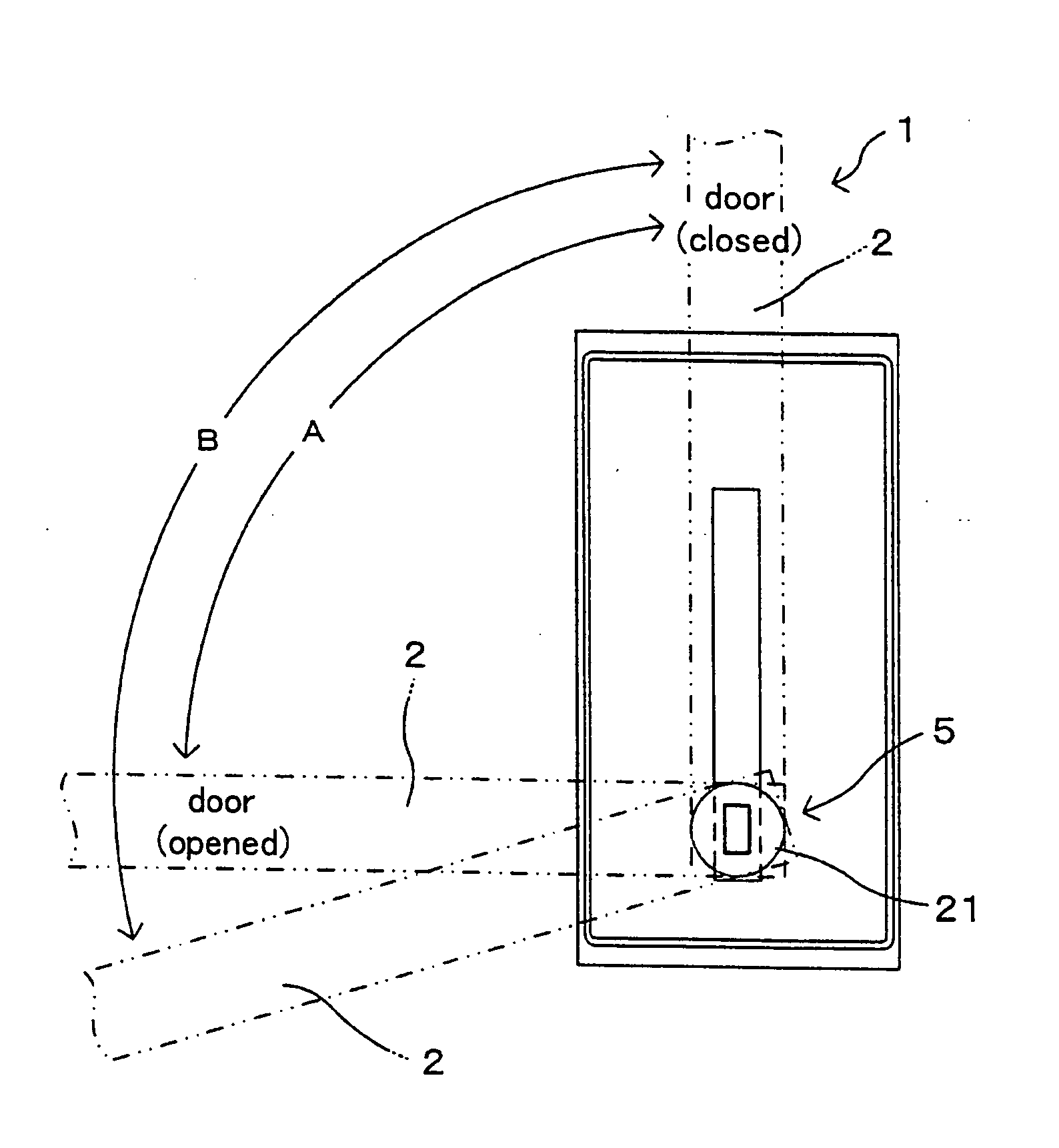
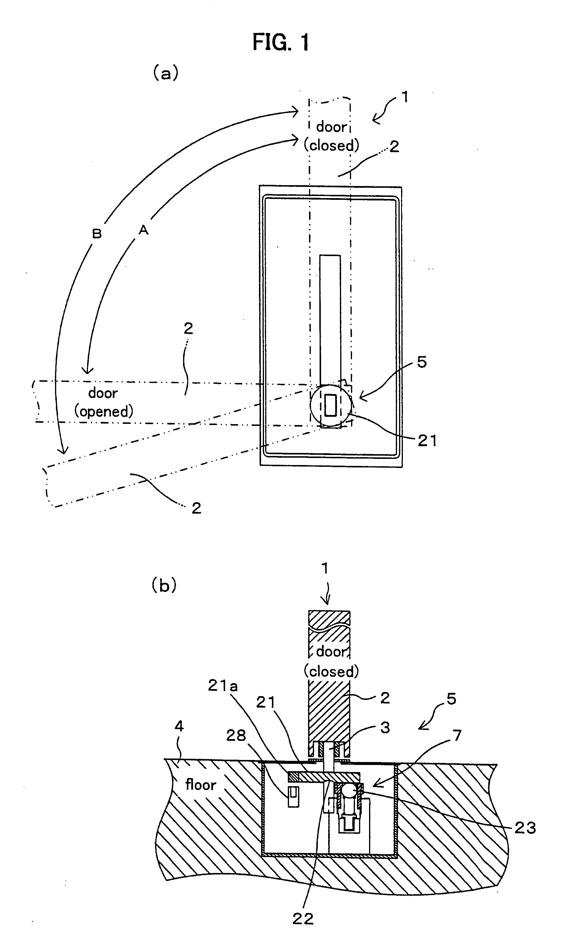
[0065] In FIGS. 1 and 2, the symbol 1 denotes a door with a door closer according to the present invention. The door with a door closer 1 comprises a door closer (not shown) for pressing the door 2 toward the closing direction, wherein a delay unit 5, which has a function for locking the rotational motion of the door 2 for a certain time (hereinafter, referred to as “first certain time”) and unlocking thereafter, is installed, connected with the rotation axis 3, around the lower part of the rotation axis 3 of the door 2 under the floor surface 4. Hereat, the place, where the delay unit 5 is installed, should not be construed as limited under the floor surface 4, but it can be inside the wall or ceiling of the building.
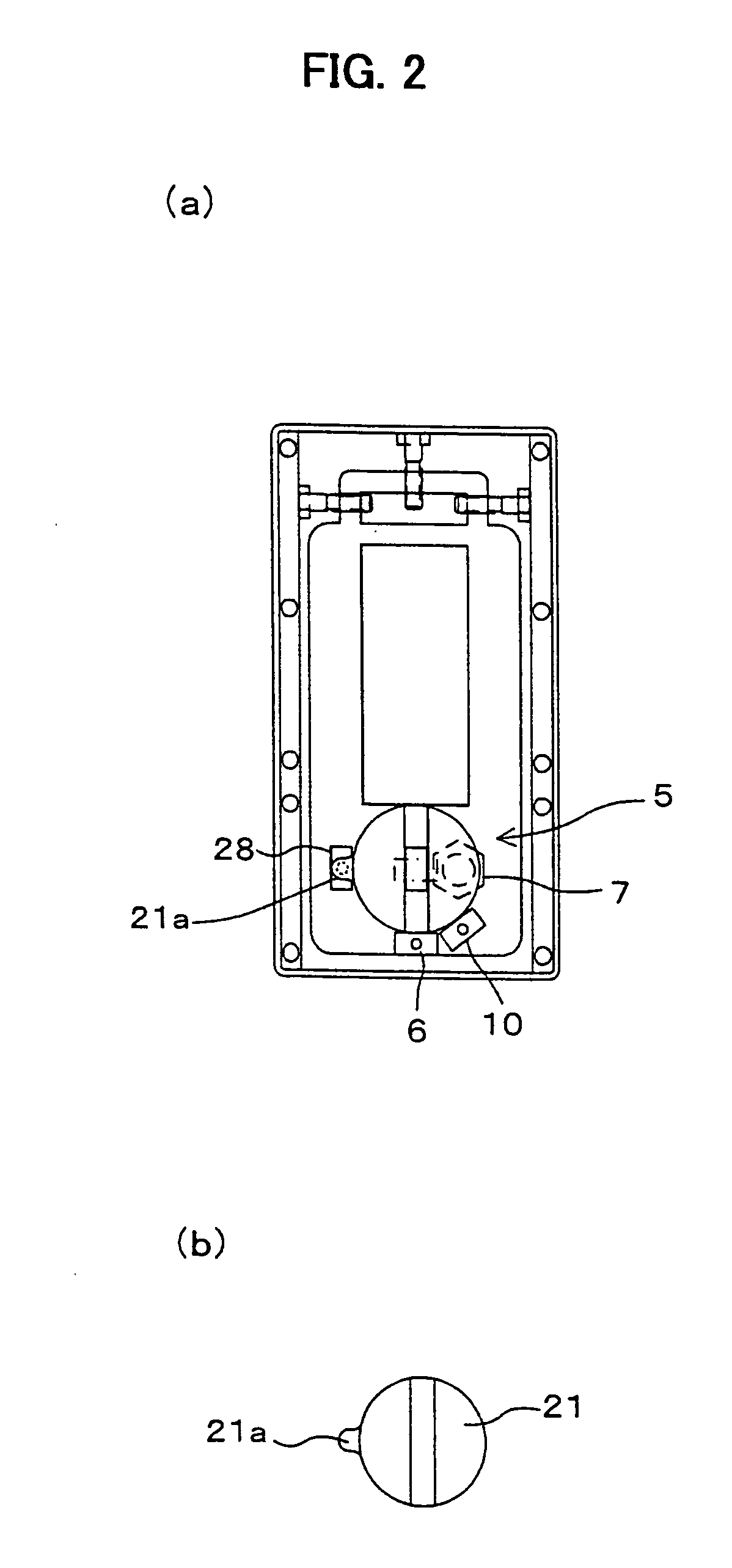
[0066] The delay unit 5 includes a first sensor 6 for detecting the door 2 having been opened to the first certain angle A (for example, 90 deg.) shown in FIG. 1(a), a lock unit 7 as electrical lock / unlock means for electronically locking and unlocking of the rotationa...
second embodiment
[0107] In FIG. 5, the symbol 31 denotes the door with a door closer according the present invention.
[0108] The door with a door closer 31 is arranged such that a lock unit 32, which is an electrical lock / unlock means of power saving type, is provided substitutionary for the lock unit (indicated by the symbol 7 in FIG. 1), which is an the electrical lock / unlock means of the delay unit (indicated by the symbol 5 in FIG. 1) provided to the aforementioned door with a door closer (indicated by the symbol 1 in FIG. 1).
[0109] The lock unit 32 includes: the lock plate 21, tightly fixed to the rotation axis 3 of the door 2, for locking the rotational motion of the rotation axis 3; as shown in FIG. 6, a lock member 34, laid inside a housing 33, for capable of freely engaging into the concave portion 22 formed on the lower surface of the lock plate 21; a front spring 35 for pressing the lock member 34; a lock piston 36 freely slidable inside the cylindrical hollow 33a formed in the housing 33...
third embodiment
[0137] In FIG. 11, the symbol 81 denotes an improved lock-unlock mechanism of the lock-unlock mechanism (indicated by the symbol 75 in FIG. 10) of the door with a door closer (indicated by the symbol 41 in FIG. 8) according to the present invention. The improved lock-unlock mechanism has a function such that the door (indicated by the symbol 2) is kept opened, when having opened to the second certain angle (for example, 110 deg.), in addition to that of the door with a door closer (indicated by the symbol 41 in FIG. 8).
[0138] The lock-unlock mechanism 81 has a structure of lock plate 49 with a lock concave portion 82 at a certain position; and the lock concave portion 82 is a concave formed on the upper surface of the lock plates 49 so as to engage with a second lock pin 83 provided differently from the lock pin 46, when the door is opened to the second certain angle. Therefore, the lock concave portion 82 is formed at the position, where the lock pin 83 locates when the door is ope...
PUM
 Abstract
Description
Claims
Application Information