Photothermal source of fluid pumping device driven by self photovoltaic power

a self-photovoltaic and pumping device technology, applied in the direction of positive displacement liquid engine, pumping device, lighting and heating apparatus, etc., can solve the problems of reducing the efficiency of converting electric power into optical power, affecting the service life of lamp device, and increasing cost, so as to save electric power and ensure safety.

Inactive Publication Date: 2012-06-21
YANG TAI HER
View PDF8 Cites 4 Cited by
  • Summary
  • Abstract
  • Description
  • Claims
  • Application Information

AI Technical Summary

Benefits of technology

[0005]The present invention provides a photothermal source of fluid pumping device driven by self photovoltaic power, wherein a light projection space defined adjacent to a photothermal source device generating both optical and thermal power is provided with a photovoltaic (PV) device capable of converting the self optical power of the photothermal source device into the electric power, and a fluid pumping device driven by the electric power supplied by the photovoltaic device is provided for pumping the gaseous or liquid fluid, so that a part or all of the photothermal source device itself, a heat radiator installed on the photothermal source device and a thermal space heated by the photothermal source device can perform the operation of thermal power transmission.
[0006]According to the present invention of the photothermal source of fluid pumping device driven by self photovoltaic power, through installing a photovoltaic device which converts the optical power into the electric power, the optical power of residual light of the photothermal source device generating both optical and thermal power is converted into electric power for driving a fluid pumping device, thus external power is not needed to be introduced so as to save electric power and safety can be ensured, and capable of being synchronously operated with the photothermal source device, so when adopted in a lamp generating both optical and thermal power, the fluid pumping device can be driven by the electric power of the photovoltaic device, so the temperature of the photothermal source device is lowered through the pumped gaseous fluid or the pumped liquid fluid, so the efficiency of electric power converting into optical power is increased and the lamp service life is prolonged; when adopted in a kerosene heater or combustion type photothermal source or electric heater with property of self generating both thermal and optical power, through installing the photovoltaic device for converting optical power to electric power, the thermal source device itself and the optical power generated with the thermal power is converted into electric power, and the electric power is served to drive the fluid pumping device, so for a part or all of the thermal source device or a heat radiator installed thereon or a thermal space heated by the thermal source device, the gaseous or liquid thermal fluid can be pumped out for transmitting thermal power or pumped in combustion assisting gaseous fluid, as such external electric power is not needed to be introduced so as to save electric power and safety can be ensured, and capable of being synchronously operated with the thermal source device, so the efficiency of heat dissipation is increased and cost is saved and less electric power is consumed.

Problems solved by technology

A conventional photothermal source device is often equipped with a property of generating both optical and thermal power, e.g. a LED driven by electric power, a light-emitting device of gas lamp tube or an electrothermal light-emitting device of electric heating wire, when being electrically charged for emitting light, thermal lose would be generated and temperature is therefore increased, so the service life of lamp device is affected and the efficiency of converting electric power into optical power is reduced, such disadvantage is often compensated by installing a large-scale heat dissipation device; as for a combustion type light-emitting device, the generated heat would also cause some disadvantages, and a photothermal source electric heating device utilizing a quartz lamp tube capable of generating both thermal and optical power or a fuel combustion heater that emits light through combustion or a combustion type photothermal source has to be installed with a fluid pumping device driven by electric power generated by an electric source so as to pump out the gaseous thermal fluid for transmitting thermal power, or to pump in combustion assisting air flow, but the shortage thereof is that the cost is raised and external electric power has to be introduced which increases the electric power consumption.

Method used


Image

  • Photothermal source of fluid pumping device driven by self photovoltaic power
  • Photothermal source of fluid pumping device driven by self photovoltaic power
  • Photothermal source of fluid pumping device driven by self photovoltaic power

Examples


Embodiment Construction

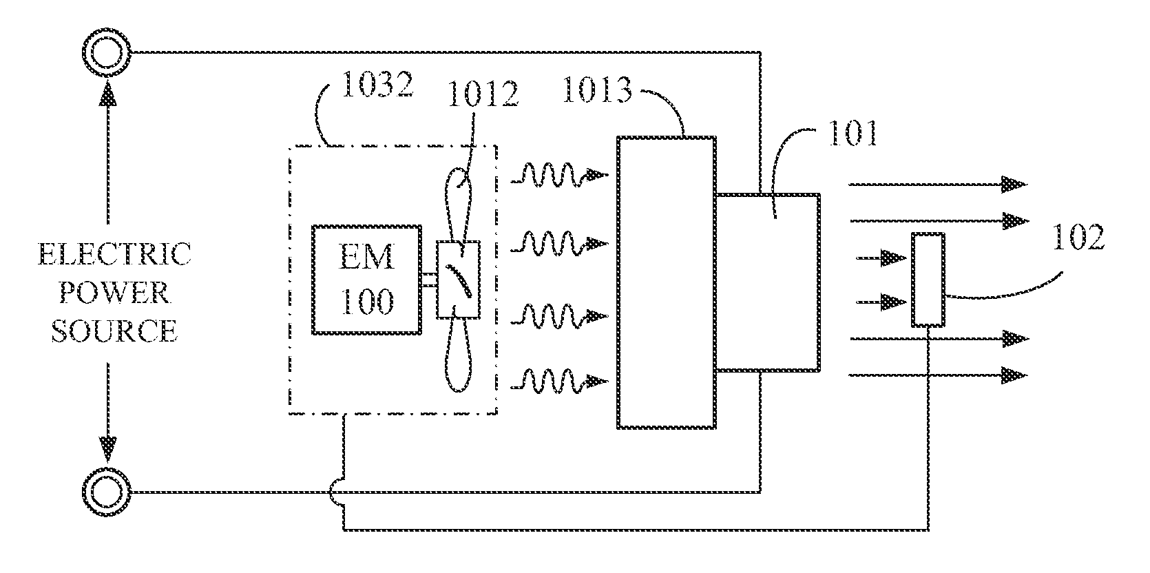
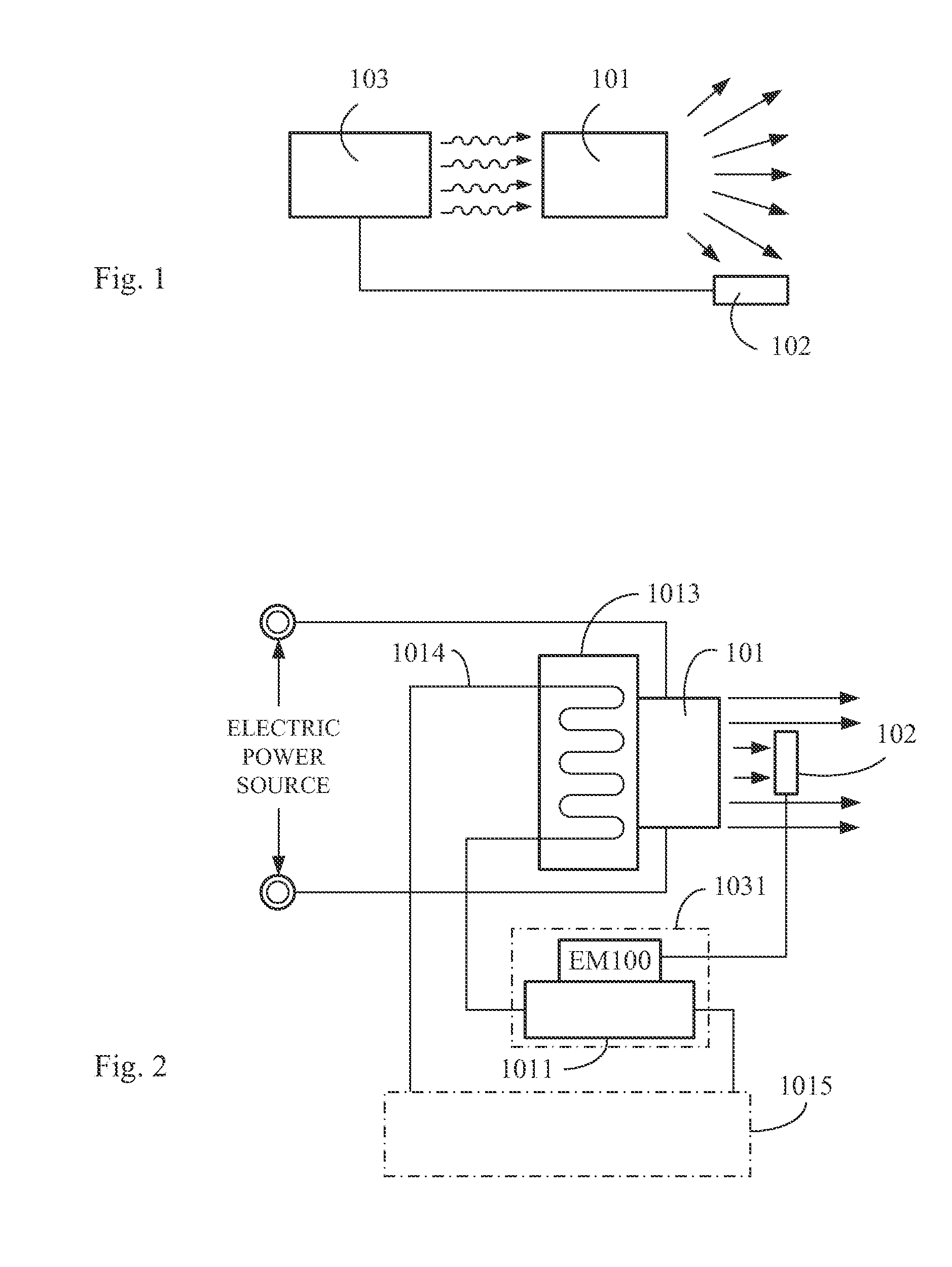
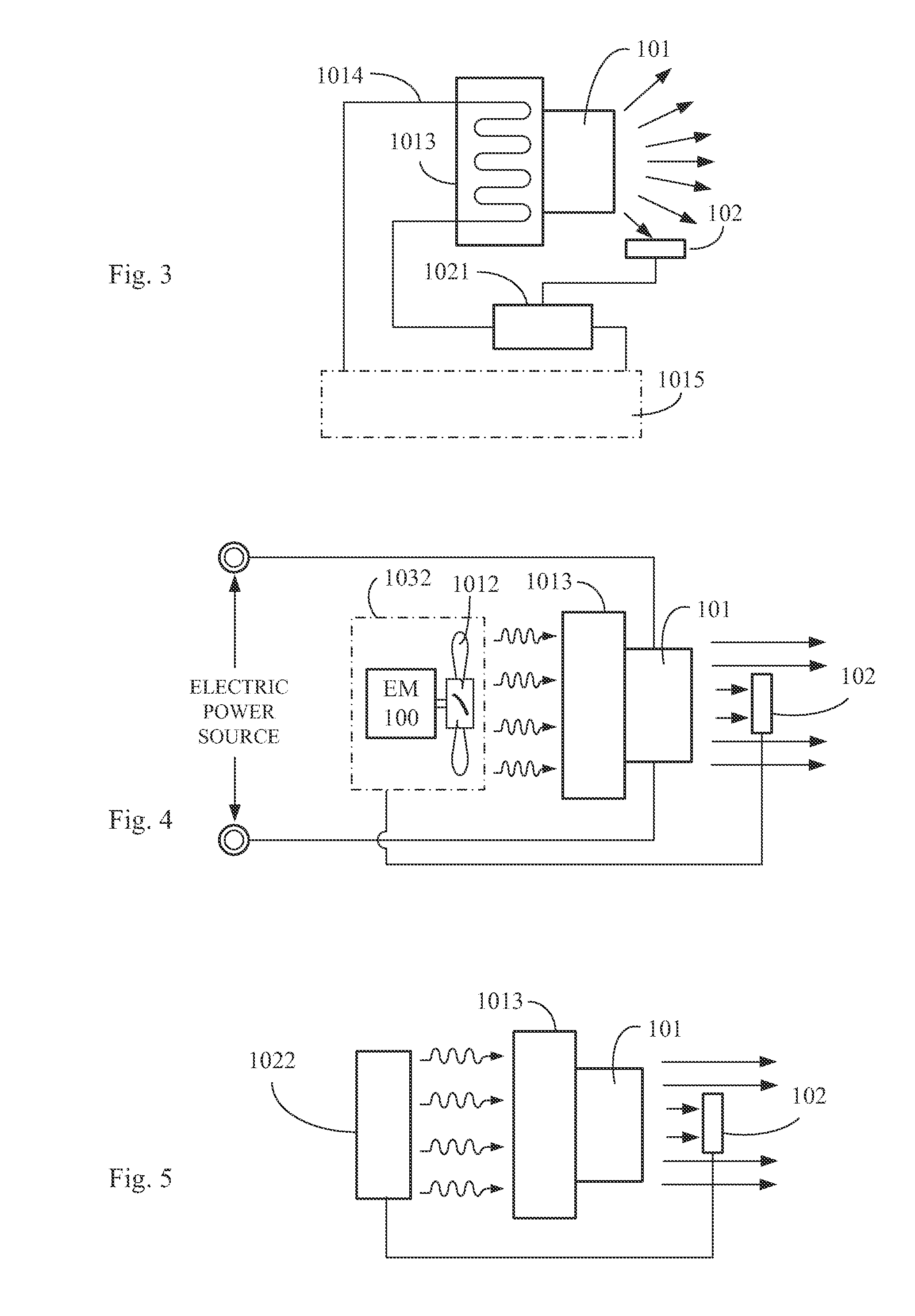
[0032]A conventional photothermal source device is often equipped with a property of generating both optical and thermal power, e.g. a LED driven by electric power, a light-emitting device of gas lamp tube or an electrothermal light-emitting device of electric heating wire, when being electrically charged for emitting light, thermal lose would be generated and temperature is therefore increased, so the service life of lamp device is affected and the efficiency of converting electric power into optical power is reduced, such disadvantage is often compensated by installing a large-scale heat dissipation device; as for a combustion type light-emitting device, the generated heat would also cause some disadvantages, and a photothermal source electric heating device utilizing a quartz lamp tube capable of generating both thermal and optical power or a fuel combustion heater that emits light through combustion or a combustion type photothermal source has to be installed with a fluid pumpin...


PUM


Abstract

The present invention relates to a photothermal source of fluid pumping device driven by self photovoltaic power, wherein a light projection space defined adjacent to a photothermal source device generating both optical and thermal power is provided with a photovoltaic (PV) device capable of converting the self optical power of the photothermal source device into the electric power, and a fluid pumping device driven by the electric power supplied by the photovoltaic device is provided for pumping a gaseous or liquid fluid, so that a part or all of the photothermal source device itself, a heat radiator installed on the photothermal source device and a thermal space heated by the photothermal source device can perform the operation of thermal energy transmission.

Description

BACKGROUND OF THE INVENTION[0001](a) Field of the Invention[0002]The present invention relates to a photothermal source of fluid pumping device driven by self photovoltaic power, wherein a light projection space defined adjacent to a photothermal source device generating both optical and thermal power is provided with a photovoltaic (PV) device capable of converting the self optical power of the photothermal source device into the electric power, and a fluid pumping device driven by the electric power supplied by the photovoltaic device is provided for pumping the gaseous or liquid fluid, so that a part or all of the photothermal source device itself, a heat radiator installed on the photothermal source device and a thermal space heated by the photothermal source device can perform the operation of thermal energy transmission.[0003](b) Description of the Prior Art[0004]A conventional photothermal source device is often equipped with a property of generating both optical and thermal ...

Claims


Application Information

Patent Timeline
Patent Type & Authority Applications(United States)
IPC IPC(8): F04D11/00H01L31/058F24H9/18F04D27/00H01L31/04
CPCF21Y2101/02F21V29/30F21Y2115/10Y02E10/50F21V29/56F21V29/60F04D27/00F24H9/18H02S10/00
Inventor YANG, TAI-HER
Owner YANG TAI HER
Why Eureka
Try Eureka