Dust collecting apparatus with a plurality of inlets

Inactive Publication Date: 2007-09-20
SAMSUNG GWANGJU ELECTRONICS CO LTD
View PDF15 Cites 31 Cited by
  • Summary
  • Abstract
  • Description
  • Claims
  • Application Information

AI Technical Summary

Benefits of technology

[0008]The present disclosure has been developed in order to overcome the above drawbacks and other problems associated with the conventional arrangement. An aspect of the present disclosure is

Problems solved by technology

Without wishing to be bound to any particular theory, it is believed that prior art dust collecting apparatus having a plurality of inlets formed at the same height result in two lumps of air that have the same speed and that crash into one another at the same height inside the cyclone chamber.
It is believed that the air molecules of the two lumps of air have a different rotation angle so that the air molecules crashing against each other results in an o

Method used


Image

  • Dust collecting apparatus with a plurality of inlets
  • Dust collecting apparatus with a plurality of inlets
  • Dust collecting apparatus with a plurality of inlets

Examples


first embodiment

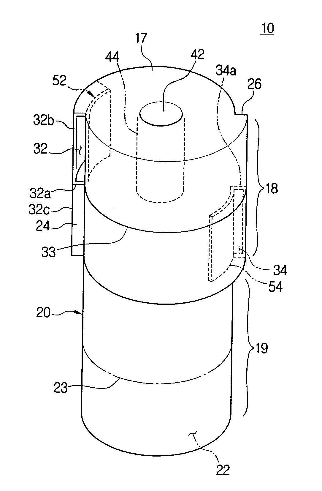
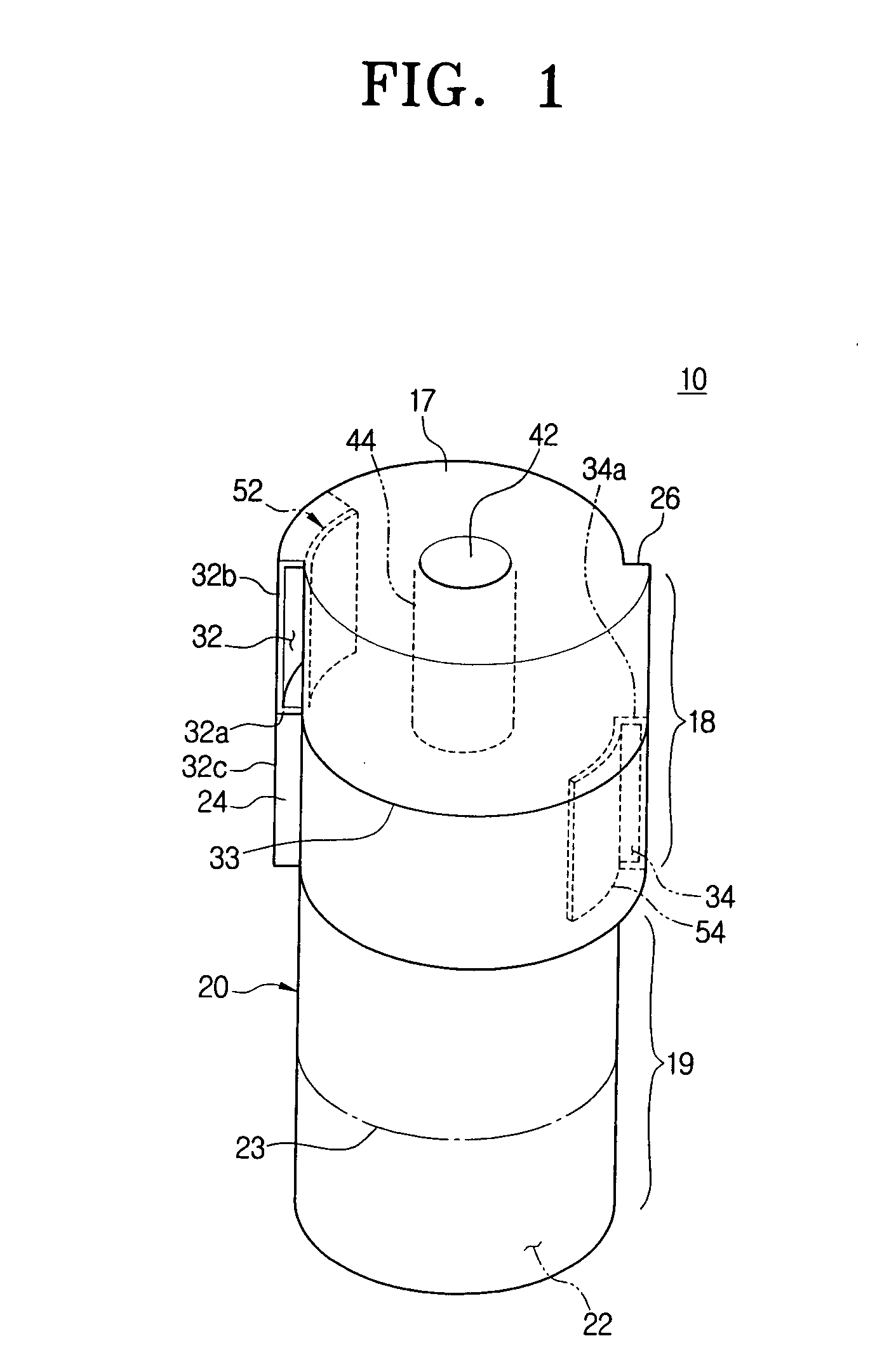
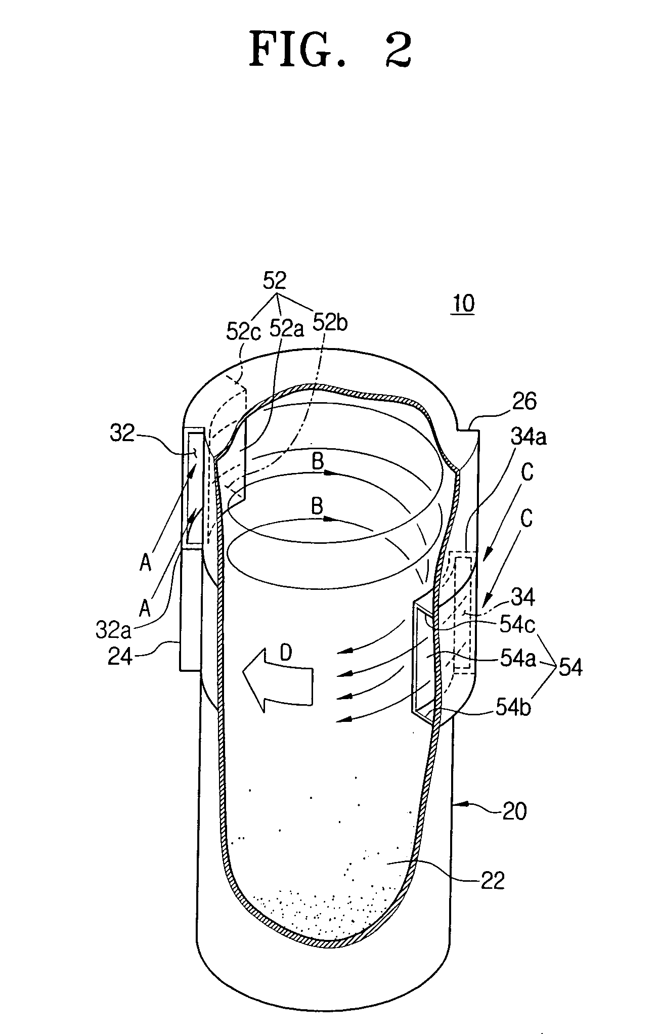
[0027]FIGS. 1 and 2 show a dust collecting apparatus 10 according to the present disclosure.

[0028]Referring to FIGS. 1 and 2, the dust collecting apparatus 10 includes a cyclone body 20, a first inlet 32, a second inlet 34, and a discharging port 42.

[0029]A top part 18 of the cyclone body 20 in which the first and second inlets 32 and 34. First inlet 32 is defined in a first projection 24 projecting from a side surface of the top part 18. Similarly, second inlet 34 is defined in a second projection 26 projecting from an opposite side surface of the top part 18. Due to first and second inlets 32 and 34, top part 18 does not have a complete circular section, but rather has a partially twisted circular section twisted as shown in FIG. 1. A bottom part 19 of the cyclone body 20 has a circular section. The bottom part 19 includes a space in which air entering through the first and second inlets 32 and 34 rotates, and a dust collecting space 22 in which dust or dirt separated from air is ...

second embodiment

[0035]FIGS. 3A and 3B show a dust collecting apparatus 110 according to the present disclosure. Here, component parts performing similar or analogous functions are labeled in multiples of one hundred.

[0036]Referring to FIG. 3A, the dust collecting apparatus 110 includes a cyclone body 120, first, second, and third inlets 132, 134, and 136, and a discharging port 142.

[0037]The cyclone body 120 includes a top part 118 and a bottom part 119. The top part 118 has first, second, and third projections 124, 126, and 128 projecting from the cyclone body 120 at angular intervals of approximate 120 degrees in a circumferential direction of the cyclone body 120. The first inlet 132 is formed at the first projection 124, the second inlet 134 is formed at the second projection 126, and the third inlet 136 is formed at the third projection 128. The bottom part 119 is formed in a cylindrical shape, and has a space at a top portion thereof for air to rotate and a dust collecting space 122 at a bott...

third embodiment

[0043]Referring to FIGS. 4 and 5, the dust collecting apparatus 210 according to the present disclosure includes a cyclone body 220, an outer housing 261, and a cover 290.

[0044]The cyclone body 220 includes an inner receptacle 221 and an inner dust receptacle 266 that can be separated from and coupled with each other. A top part 218 of the inner receptacle 221 has a first inlet 232, a second inlet 234 formed at an approximate 180 degrees from the first inlet 232, and a discharging port 242 formed at a top surface thereof. A bottom part 219 of the inner receptacle 221 has a substantially cone shape having a diameter decreasing from a top end to a bottom end unlike the first and second embodiments. A skirt 223 is formed at a bottom end of the bottom part 219, and prevents dust collected in an outer dust receptacle 264 from flowing back toward the first and second inlets 232 and 234. The inner dust receptacle 266 is formed integrally with the outer dust receptacle 264 using an injectio...


PUM

PropertyMeasurementUnit
Angleaaaaaaaaaa
Areaaaaaaaaaaa
Heightaaaaaaaaaa

Abstract

The present disclosure relates to a dust collecting apparatus. The dust collecting apparatus includes a cyclone body forming a cyclone chamber; a plurality of inlets formed at the cyclone body, and causing air to enter through; and a discharging port formed at the cyclone body, and discharging the air from the cyclone chamber, wherein each inlet of the plurality of inlets is formed at a different height at a side of the cyclone body so that the air is divided to enter the cyclone chamber at a different height.

Description

[0001]This application claims the benefit under 35 U.S.C. §119(a) of Korean Patent Application No. 10-2006-0023915, filed Mar. 15, 2006, the entire contents of which are hereby incorporated by reference.BACKGROUND OF THE INVENTION[0002]1. Field of the Invention[0003]The present disclosure relates to a dust collecting apparatus. More particularly, the present disclosure relates to a dust collecting apparatus that draws in air and separates dust or dirt from the air.[0004]2. Description of the Related Art[0005]Generally, dust collecting apparatuses separating dust from air are used in household or industrial vacuum cleaners. Especially, cyclone dust collecting apparatuses, which force air to whirl and separate dust or dirt from the air using a centrifugal force without a dust bag, have been developed and used in various vacuum cleaners.[0006]The conventional dust collecting apparatus has an inlet through which air enters at a side of an upper part of a cyclone body. Therefore, air ent...

Claims


Application Information

Patent Timeline
IPC IPC(8): B01D45/12
CPCA47L9/165B04C5/04B01D45/12Y10S55/03
Inventor LEE, DONG-YUN
Owner SAMSUNG GWANGJU ELECTRONICS CO LTD
Why Eureka
Try Eureka