Check valve mechanism for rodents and/or odors

a check valve and rodent technology, applied in the field of plumbing accessories, can solve problems such as obstruction of passages

Inactive Publication Date: 2007-09-20
FARRUGGIA PASQUALE
View PDF22 Cites 6 Cited by
  • Summary
  • Abstract
  • Description
  • Claims
  • Application Information

AI Technical Summary

Problems solved by technology

The wires move radially inward, and hence obstruct the passage when pressed by the animal.

Method used


Image

  • Check valve mechanism for rodents and/or odors
  • Check valve mechanism for rodents and/or odors
  • Check valve mechanism for rodents and/or odors

Examples


Embodiment Construction

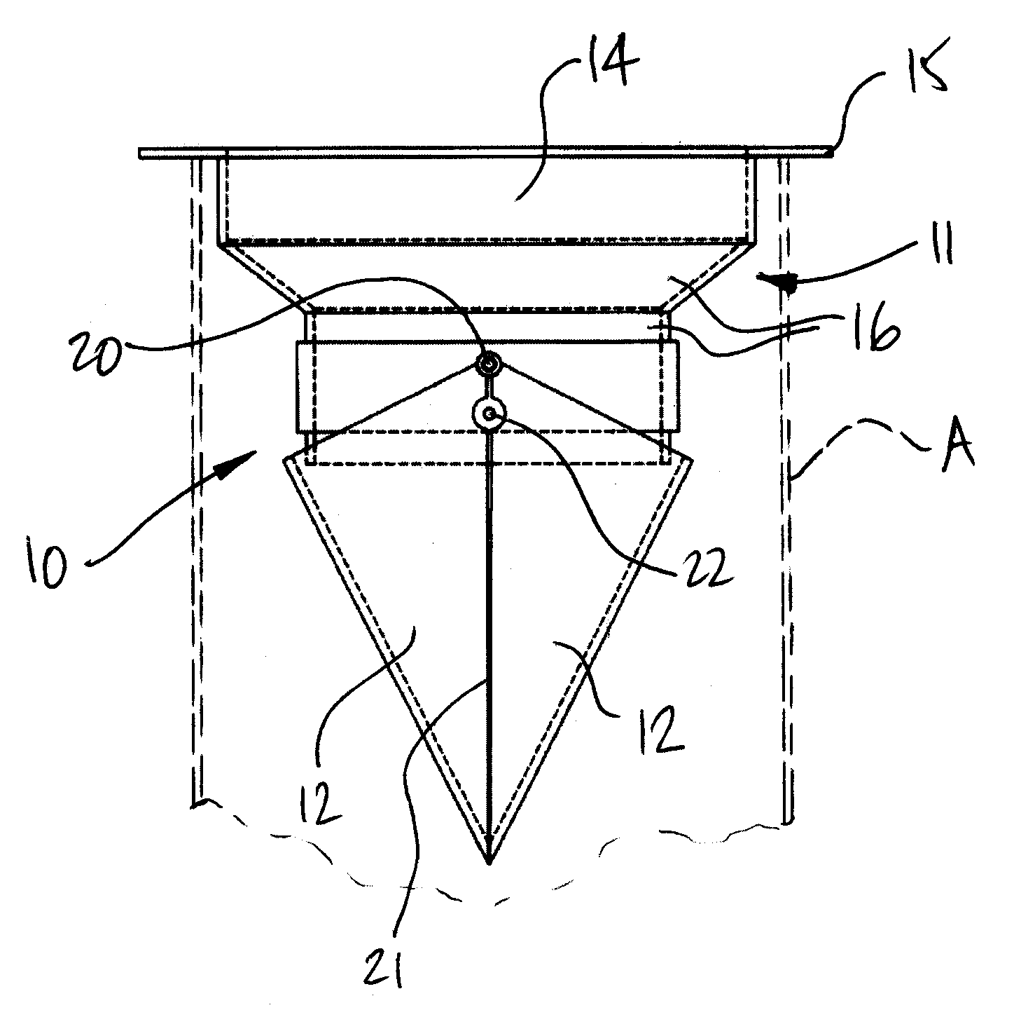
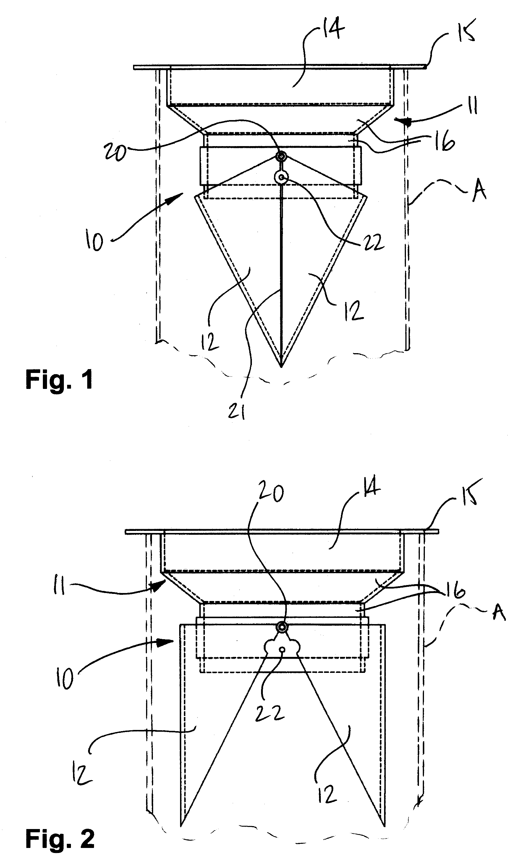
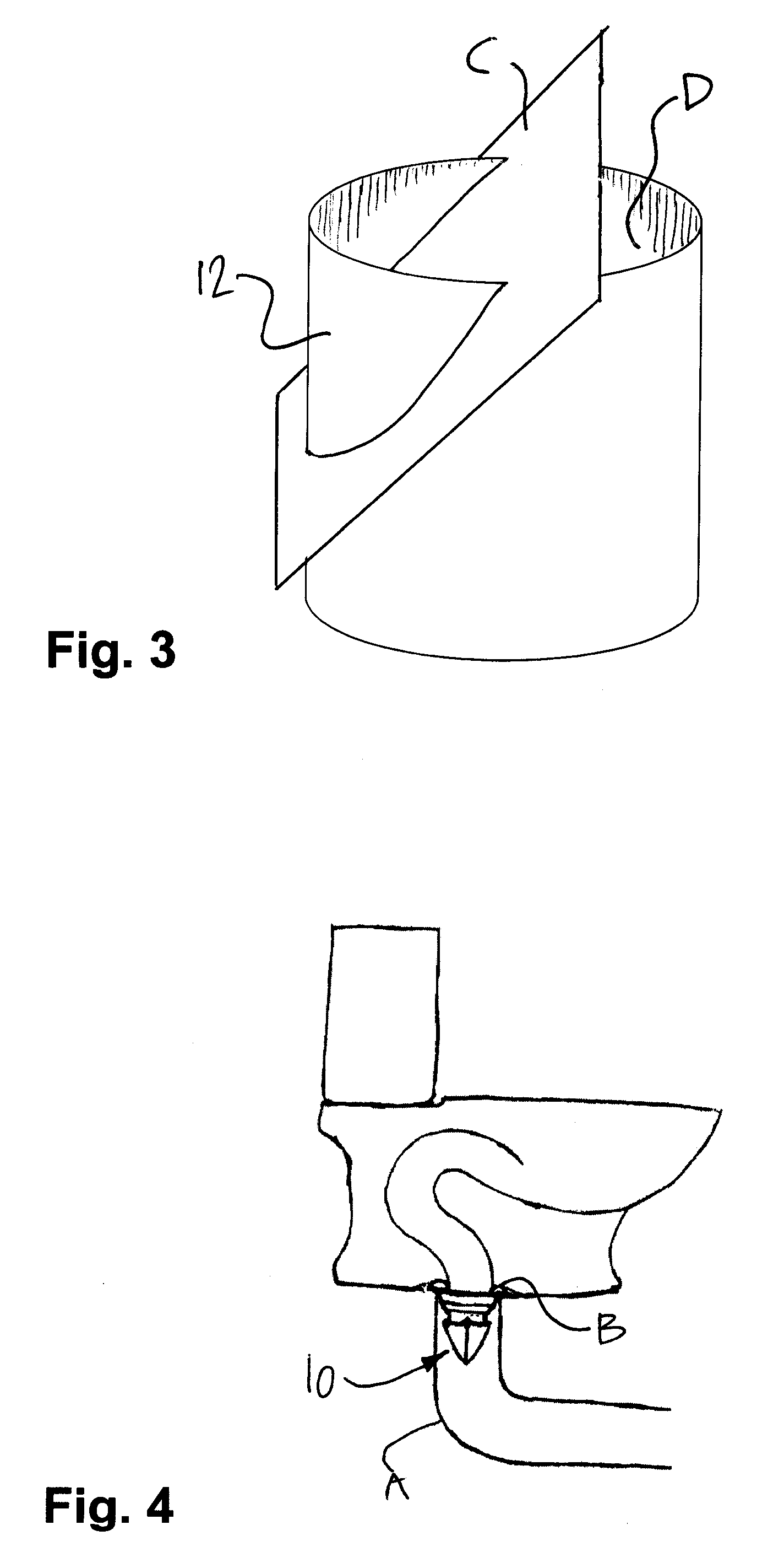
[0022]Referring to FIGS. 1 and 2, a check valve mechanism constructed in accordance with the present invention is generally shown at 10, with respect to a drain pipe A. The check valve mechanism 10 has a connector portion 11 and flaps 12, by which it will be connected to a drain pipe (as shown in FIGS. 4 and 6).

[0023]The connector portion 11 is provided as the interface between the flaps 12 the drain pipe A. The flaps 12 are pivotally mounted to the connector portion 11.

[0024]The flaps 12 form the barrier that will block the drain pipe A against infiltration by rodents. In an alternative embodiment, the flaps 12 will generally block odors.

[0025]The connector portion 11 has a tubular body 14 and a flange 15 at a top end of the tubular body 14. The tubular body 14 is sized so as to fit within the drain pipe. The flange 15, on the other hand, as a diameter larger than that of the drain pipe, so as to be seated on the drain pipe, as is shown in FIG. 4. It is shown in FIG. 4 that the che...


PUM


Abstract

A check valve mechanism for use with a vertical drain pipe comprises a connector portion for supporting the check valve mechanism with respect to the drain pipe, and two flaps, each being an ungula of a cylindrical tube. The flaps are pivotally connected to the connector portion, so as to be displaceable between a closed position in which the flaps are against one another such that peripheral portions of the flaps are collinear at a connection line to obstruct the drain pipe, and an opened position, in which the flaps are away from one another to allow liquids/solids to pass through the check valve mechanism and the flaps.

Description

CROSS-REFERENCE TO RELATED APPLICATION[0001]This patent application claims priority on U.S. Provisional Patent Application No. 60 / 782,620, filed on Mar. 16, 2006, by the present applicant.BACKGROUND OF THE INVENTION[0002]1. Field of the Invention[0003]The present invention generally relates to plumbing accessories used in draining systems and sewer systems and, more particularly, to a check valve mechanism forming a rodent barrier for drain pipes, and forming an odor barrier for floor drains.[0004]2. Background Art[0005]One of the primary functions of drain pipes is to provide a conduit for the evacuation of human waste toward sewer systems. Accordingly, check valve systems or like rodent barriers have been used to allow the evacuation of human waste therethrough, while blocking the pipes to prevent infiltration by rodents. U.S. Pat. No. 5,481,766, issued to Steadman on Jan. 9, 1996, describes a toilet guard consisting of a guard tube and a plurality of flexible, resilient wires hav...

Claims


Application Information

Patent Timeline
Patent Type & Authority Applications(United States)
IPC IPC(8): F16K15/03
CPCE03C1/298F16K15/038E03F7/06E03D11/10Y10T137/7898Y10T137/7838
Inventor FARRUGGIA, PASQUALE
Owner FARRUGGIA PASQUALE
Why Eureka
Try Eureka