Fluid dispensing valve assembly

a technology of dispensing valves and components, which is applied in the direction of liquid transferring devices, transportation and packaging, pliable tubular containers, etc., can solve the problems of dispensing valve failure, simple devices that do not provide reliable use, and expensive devices for dispensing fluids, etc., to achieve convenient use, convenient replacement, and economical manufacturing

Inactive Publication Date: 2000-04-25
KOLLER ENTERPRISES +1
View PDF35 Cites 96 Cited by
  • Summary
  • Abstract
  • Description
  • Claims
  • Application Information

AI Technical Summary

Benefits of technology

Accordingly, among the several objects of this invention may be noted the provision of a dispenser that dispenses a pre-determined amount of fluid upon each actuati...

Problems solved by technology

Such dispensers include either expensive devices for dispensing the fluid or simple devices that do not provide reliable use over an extended period of t...

Method used


Image

  • Fluid dispensing valve assembly
  • Fluid dispensing valve assembly
  • Fluid dispensing valve assembly

Examples


Embodiment Construction

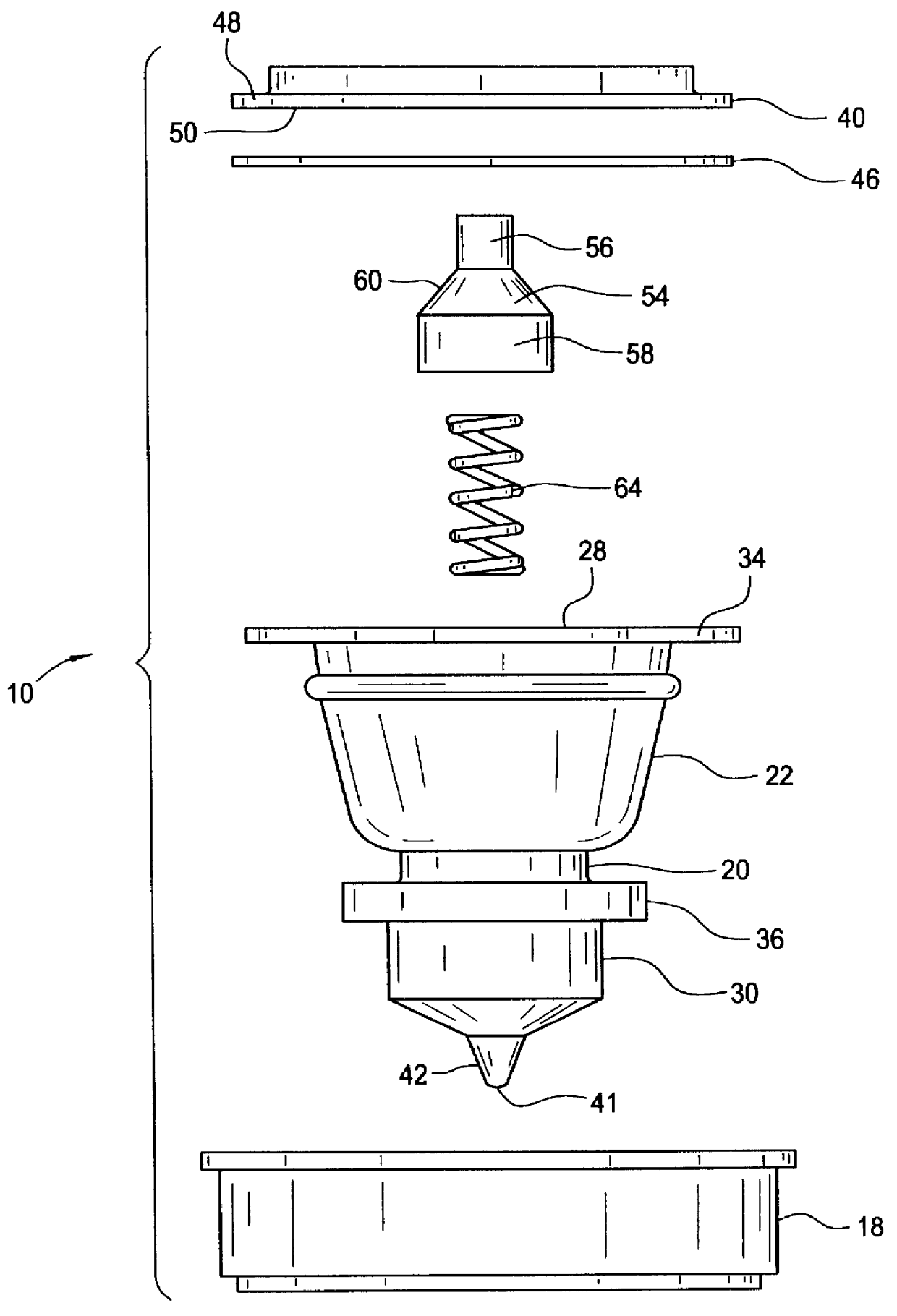
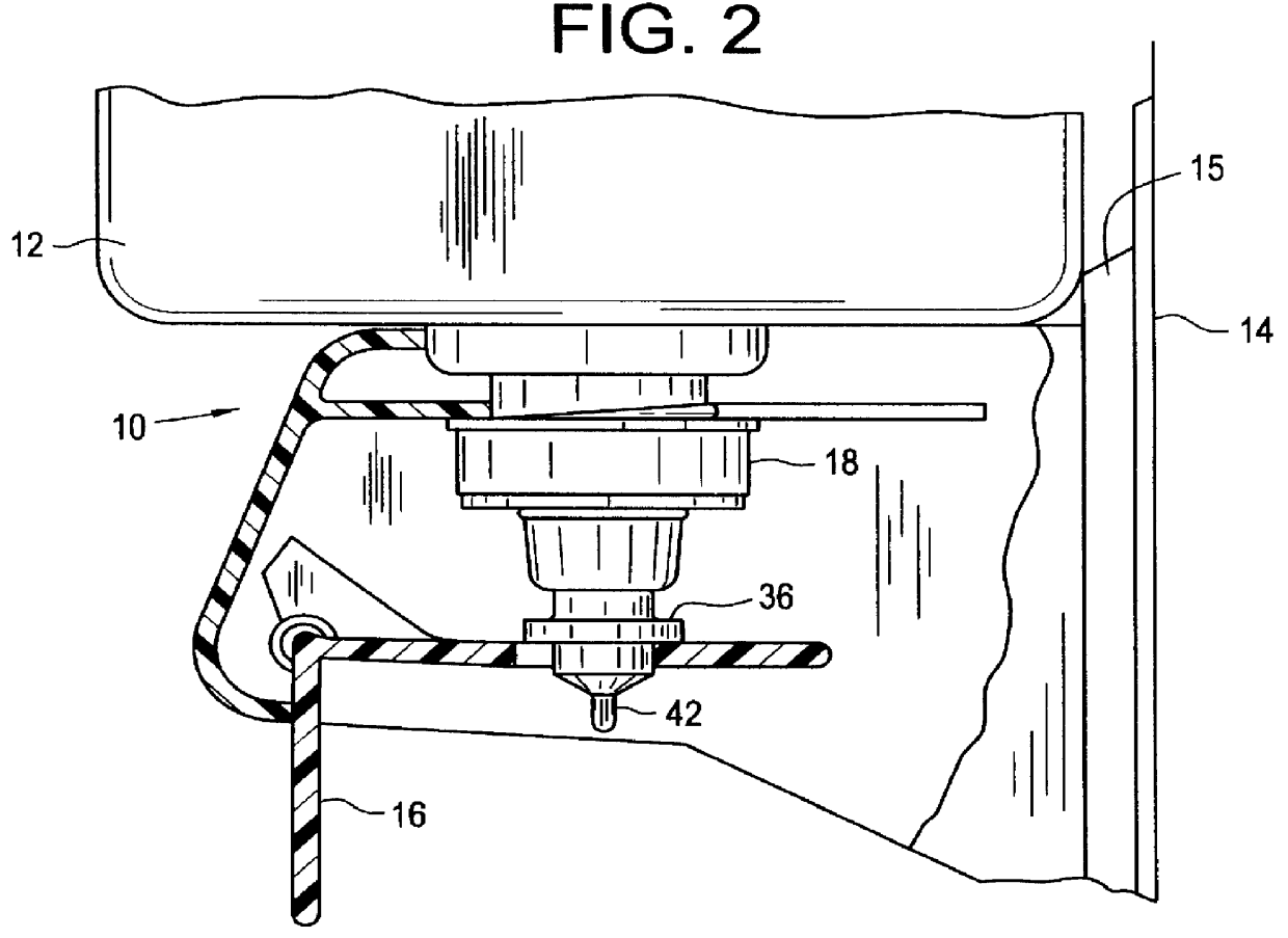
Referring to the drawings, first to FIGS. 1 and 2, there is generally indicated at 10 a fluid dispenser of this invention operable to dispense a fluid such as soap or lotion from a container 12. The dispenser 10 is applicable to a mouth of the container 12 with the container in an inverted position and the mouth down. The container 12 is mounted on a wall 14 or other suitable support surface by means of a container holder 15 and includes a lever 16 for actuating the dispenser 10 (FIG. 2). The dispenser 10 is fitted within a cap 18 which is threaded onto the container 12 over the mouth for dispensing the fluid. The dispenser 10 is movable in an upward direction relative to the inverted container 12 through a pressure stroke for delivering a charge of fluid to a user and in a downward direction relative to the inverted container through a return stroke to a dispenser recharging position.

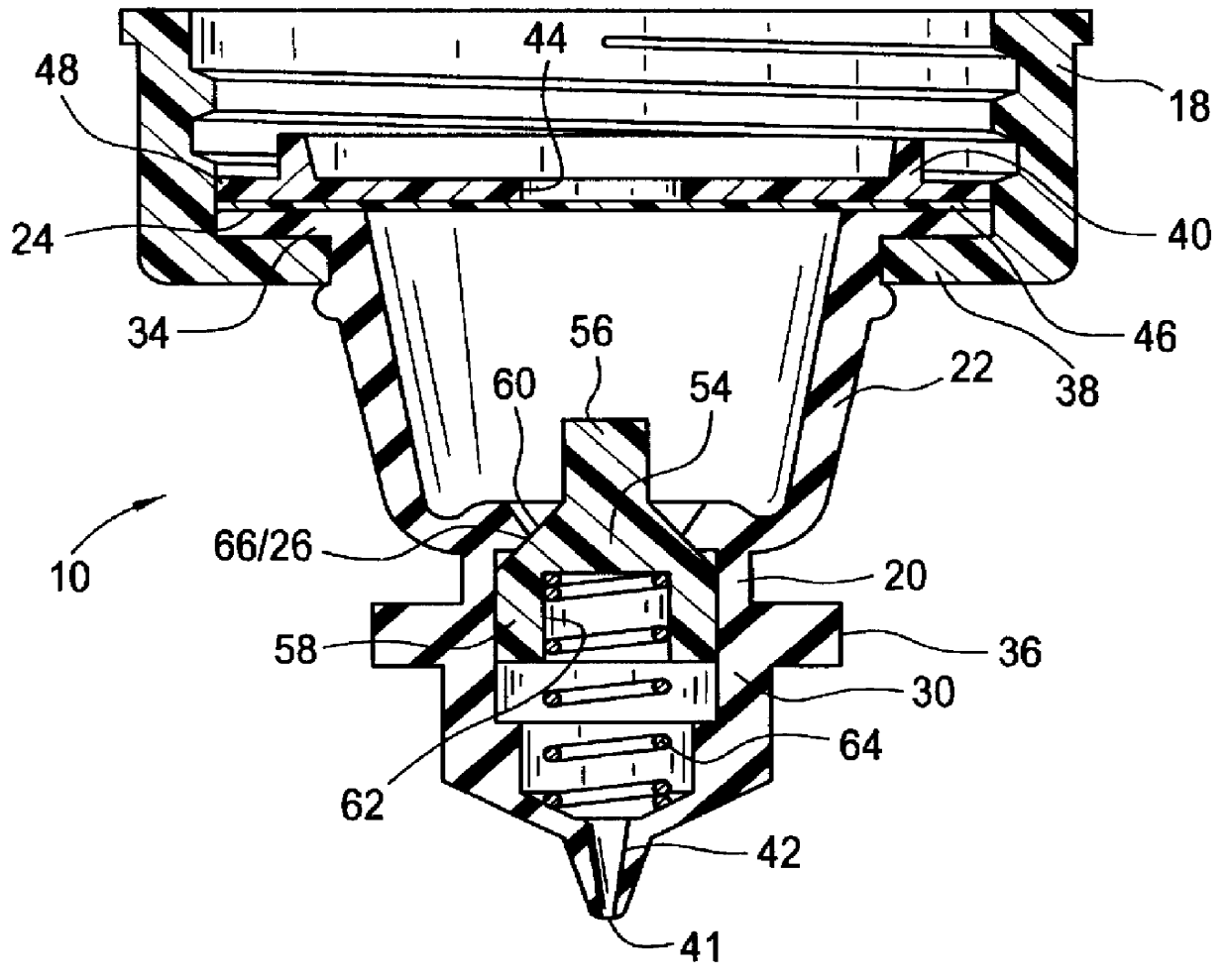
The preferred embodiment of the dispenser 10, as shown in FIGS. 1-6, includes a body, generally ind...


PUM


Abstract

A dispenser for dispensing charges of fluid from a container and applicable to a mouth of the container with the container in an inverted position and the mouth down. The dispenser includes a body formed of resilient elastomeric material having a hollow annular upper part having a flexible, resilient annular wall and an upper and lower end and constituting a bellows which is downwardly expansible and upwardly contractible by flexing of the annular wall. The body has integral with the bellows a lower part having a discharge port. The dispenser includes a first check valve at an entry end of the bellows operable for flow of fluid into the bellows on expansion thereof and operable to block flow of fluid from the pump member out of its upper end on contraction thereof. A second valve is operable for dispensing the charge of fluid from the bellows down into the outlet nozzle on contraction of the bellows and to block flow out of the bellows outlet on expansion of the bellows. The second check valve has a valve seat member at the intake of the bellows and outlet nozzle, has at least one outlet port below the valve and a spring biased to keep the poppet valve seated against the valve seat such that the fluid is expelled through the poppet valve, outlet nozzle, and outlet port on contraction of the pump member.

Description

BRIEF SUMMARY OF THE INVENTIONThis invention relates generally to fluid dispensing valves and more particularly to dispensing valves of the type suitable for dispensing fluids such as soaps, hand cleaners and lotions. Such dispensers include either expensive devices for dispensing the fluid or simple devices that do not provide reliable use over an extended period of time. Many dispensing valves fail over time due to warpage of internal parts which results in excessive leakage of the fluid creating a mess under the dispenser. It is further desirable to easily replace the valve if the valve becomes damaged without discarding the entire fluid dispenser.Accordingly, among the several objects of this invention may be noted the provision of a dispenser that dispenses a pre-determined amount of fluid upon each actuation and which is reliable over an extended period of time and readily replaceable; and the provision of such a dispenser which is economical to manufacture and easy to use.Gen...

Claims


Application Information

Patent Timeline
IPC IPC(8): B65D47/24B65D47/04
CPCB65D47/249
Inventor LUDBROOK, GREGORY S.STEVENS, JR., EDWARD R.
Owner KOLLER ENTERPRISES
Why Eureka
Try Eureka