Beverage forming apparatus with centrifugal pump

a centrifugal pump and beverage technology, applied in beverage vessels, domestic applications, kitchen equipment, etc., can solve the problems of non-self-priming pump air boundness and useless brewers, and achieve the effect of preventing substantial leakag

Active Publication Date: 2012-04-10
KEURIG GREEN MOUNTAIN INC
View PDF20 Cites 96 Cited by
  • Summary
  • Abstract
  • Description
  • Claims
  • Application Information

AI Technical Summary

Benefits of technology

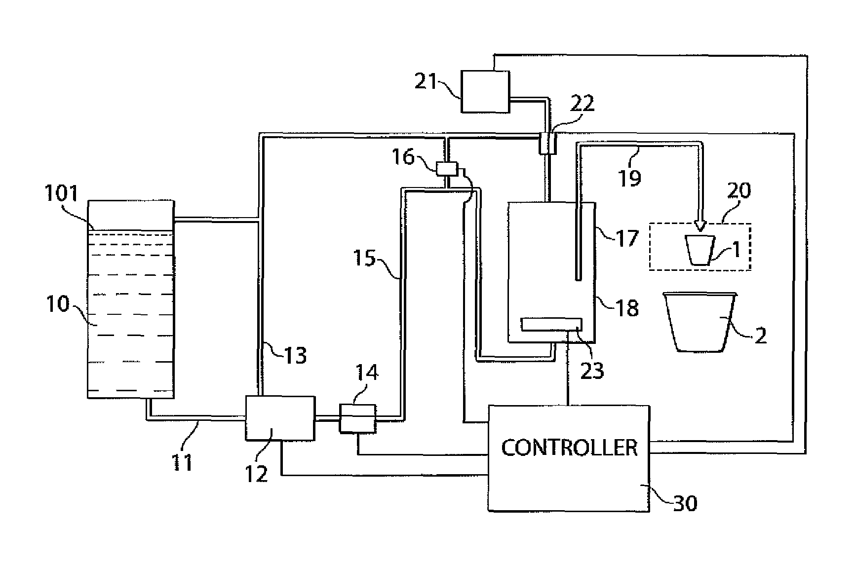
[0007]Aspects of the invention provide the ability to employ a non-self-priming pump type, such as a centrifugal pump, in a brewer or other beverage forming apparatus, even when the brewer includes a removable water storage tank. For example, in one aspect of the invention, a centrifugal pump includes a priming vent that allows water to flow into the pump to a sufficient level to allow the pump to prime itself. The priming vent may remain permanently open, yet not interfere with pump operation, e.g., allow the pump to develop sufficient pressure to provide water suitable for brewing. The priming vent may be connected to the storage tank, e.g., so that any flow occurring from the priming vent during pump operation can be routed into the water storage tank for re-supply to the pump. The priming vent may be positioned below a full level of the storage tank where a top level of water in the tank is located when the storage tank is full. This may help gravity-fed water to flow into the pump for priming.
[0008]In another aspect of the invention, a liquid supply circuit that provides liquid from a storage tank to a metering tank may include a centrifugal pump and a check valve or other backflow preventer downstream of the pump that opens to allow one-way flow when there is a suitable pressure difference across the device. The backflow preventer may allow the pump to deliver liquid to the metering tank, yet prevent flow from the metering tank to the pump, e.g., caused by a siphon. Even if the backflow preventer prevents liquid from flowing under the pull of gravity from the storage tank to the centrifugal pump to prime the pump, e.g., because the pressure developed by gravity is not sufficient to open the check valve or other device, the priming vent in the centrifugal pump may allow sufficient flow of liquid and venting of air to allow the pump to be primed. In one embodiment, the priming vent may remain open at all times, even during operation of the pump, thus allowing a relatively inexpensive priming arrangement that does not require valve opening / closing control.
[0009]Another aspect of the invention provides for a vent in a conduit between a pump and a metering tank in a brewer, e.g., to help prevent a backflow of liquid from the metering tank to the pump and / or to help resist leaking of a backflow preventer, such as a check valve, in the conduit. The inventors have found that a check valve in a conduit between a supply pump and a metering tank that is intended to prevent backflow from the metering tank to the pump can sometimes leak, particularly if the pressure in the conduit downstream of the check valve is relatively high. In accordance with aspects of the invention, a vent is provided to relieve pressure in the conduit downstream of the backflow preventer, thereby helping to resist unwanted backflow of liquid. In another aspect of the invention, the vent may break a siphon in the conduit between the pump and the metering tank. This may also help prevent unwanted backflow, even if there is no check valve or other backflow preventer. In one embodiment, the conduit between the pump and the metering tank may be routed to a point above a top of the metering tank so that formation of a gravity-driven siphon can be prevented.
[0012]In one embodiment, the vent valve and the priming vent may be connected to the storage tank by a common conduit. The vent valve may connect to the pump conduit downstream of the flow control valve (if provided) at a point above a top of the metering tank. Such an arrangement may help break a siphon that might otherwise form between the metering tank and the centrifugal pump.
[0013]In another embodiment, the priming vent may always be open and connected to ambient air pressure. For example, the priming vent may include a suitably sized orifice that allows sufficient flow of air to prime the centrifugal pump, yet restrict flow of liquid so as prevent substantial leakage while the pump is operating.

Problems solved by technology

Such air may cause a non-self priming pump to become air bound and fail in pumping water from the storage tank to other portions of the brewer when the storage tank is re-connected to the brewer.
This can present a significant problem, especially where the home user has no way in which to prime the pump.
For example, a brewer manufacturer that uses a non-self priming pump that somehow becomes air bound and is incapable of pumping brew water will render the brewer useless.

Method used


Image

  • Beverage forming apparatus with centrifugal pump
  • Beverage forming apparatus with centrifugal pump
  • Beverage forming apparatus with centrifugal pump

Examples


Embodiment Construction

[0021]It should be understood that aspects of the invention are described herein with reference to the figures, which show illustrative embodiments in accordance with aspects of the invention. The illustrative embodiments described herein are not necessarily intended to show all aspects of the invention, but rather are used to describe a few illustrative embodiments. Thus, aspects of the invention are not intended to be construed narrowly in view of the illustrative embodiments. In addition, it should be understood that aspects of the invention may be used alone or in any suitable combination with other aspects of the invention.

[0022]FIGS. 1 and 2 show a perspective view and a side view, respectively, of a beverage forming apparatus 100 that incorporates one or more aspects of the invention. Although the beverage forming apparatus 100 may be used to form any suitable beverage, such as tea, coffee, other infusion-type beverages, beverages formed from a liquid or powdered concentrate,...


PUM


Abstract

A beverage forming apparatus includes a storage tank, and a centrifugal pump having an inlet connected to the storage tank by a supply conduit. The centrifugal pump may include a priming vent located below a full level of the storage tank and permit air to vent as liquid primes the pump. A metering tank may have an inlet connected to the centrifugal pump by a pump conduit, and an outlet connected to a brew chamber that forms a beverage using liquid received from the metering tank. In one embodiment, a flow control valve, such as a check valve, may be provided in the pump conduit to allow flow from the pump to the metering tank, but resist flow in reverse. In another embodiment, a vent valve in the pump conduit may be arranged to vent at least a portion of the pump conduit, e.g., to ambient air pressure.

Description

BACKGROUND[0001]1. Field of Invention[0002]This invention relates to beverage forming machines, such as beverage brewing machines that form a beverage using a cartridge.[0003]2. Related Art[0004]Beverage forming machines commonly include a water supply, such as a storage tank or plumbed connection to a municipal source. Particularly for machines having a storage tank, a pump or other device is often needed to deliver water from the storage tank to various parts of the machine, such as a brew chamber where the water is mixed with a beverage medium to form a beverage.[0005]Some coffee brewers made by Keurig, Incorporated of Reading, Mass. include a solenoid-operated pump to deliver water from a storage tank to a metering chamber where the water is heated. The solenoid-operated pumps include one or more check valves or other backflow preventer that prevents water from flowing in reverse direction from the metering tank to the storage tank.SUMMARY OF INVENTION[0006]The inventors have ap...

Claims


Application Information

Patent Timeline
Patent Type & Authority Patents(United States)
IPC IPC(8): A47J31/36
CPCA47J31/46A47J31/468A47J31/469
Inventor JACOBS, WILLIAM T.SHEPARD, JAMES E.SULLIVAN, KEVIN P.TINKLER, IAN
Owner KEURIG GREEN MOUNTAIN INC
Why Eureka
Try Eureka