Controlling fuel cell fuel purge in response to recycle fuel blower operating conditions

a technology of fuel cell and operating conditions, which is applied in the direction of cell components, electrochemical generators, cell component details, etc., can solve the problems of reducing system power performance, fuel cell power plants cannot be run at 100% fuel utilization, and fuel starvation in various regions, so as to improve the startup and shutdown of fuel cell power plants, effective control of fuel cell anode purge, and adequate fuel flow

Inactive Publication Date: 2006-01-05
INT FUEL CELLS
View PDF16 Cites 35 Cited by
  • Summary
  • Abstract
  • Description
  • Claims
  • Application Information

AI Technical Summary

Benefits of technology

[0006] Objects of the invention include: a simple, effective control over fuel cell anode purge which does not require additional equipment; providing information on hydrogen flow through the anode of a fuel cell without the need of hydrogen sensors; providing improved startup and shutdown of fuel cell power plants; providing purge control in a fuel cell power plant which is responsive to actual conditions in the anode fuel flow; assuring adequate fuel flow in a fuel cell power plant without marginal extra flow; and fuel cell power plant anode purge which is responsive to actual gas composition of the anode gas flow.

Problems solved by technology

It is well known that fuel cell power plants cannot be run at 100% fuel utilization, that is, providing the exact amount of fuel which is consumed in producing the desired electrical load, without resulting in fuel starvation at various regions of various fuel cells in the stack.
Fuel cell starvation results in corrosion of the carbonaceous catalyst supports, resulting in reduced system power performance.
The problem with this method is that it fails to take into account surges and variations in nitrogen crossover due to changes in the membrane, performance losses in the fuel cell, and so forth.
To overcome these problems, the purge is purposely set somewhat high, providing a marginal purge to assure that the purge will be sufficient; this naturally reduces the efficiency of the overall system below that which could possibly be attained.
If the purge gas is released into a cabinet containing the fuel cell systems, the marginal, extra purge also increases on the cabinet ventilation system which increases the noise level and the parasitic power loss.

Method used


Image

  • Controlling fuel cell fuel purge in response to recycle fuel blower operating conditions
  • Controlling fuel cell fuel purge in response to recycle fuel blower operating conditions
  • Controlling fuel cell fuel purge in response to recycle fuel blower operating conditions

Examples


Embodiment Construction

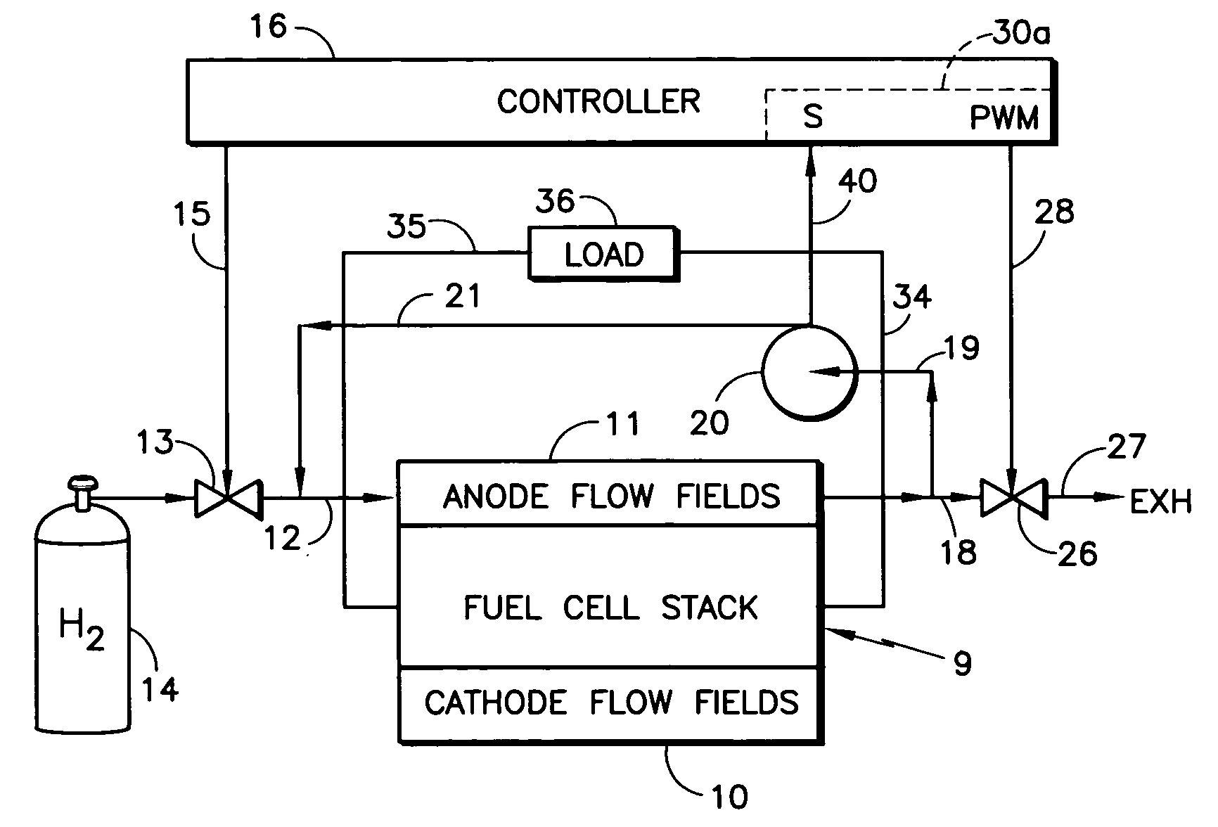
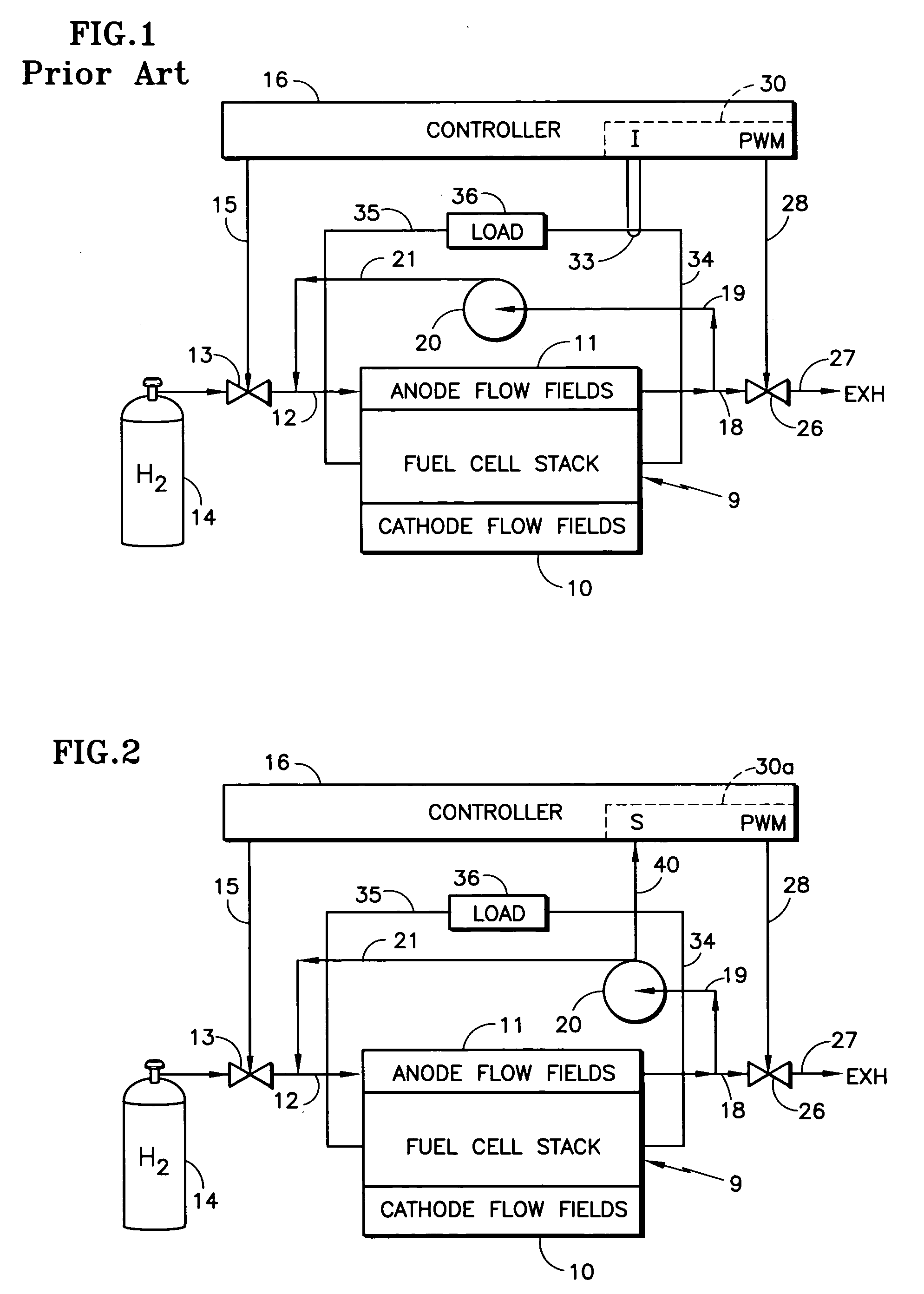
[0015] Referring to FIG. 1, a fuel cell stack 9 includes cathode flow fields 10, and includes anode flow fields 11 which are provided with fuel reactant gas in a fuel inlet conduit 12 through a valve 13 from a source 14 of fuel, such as hydrogen. The fuel exhaust in a conduit 18 provides fuel recycle gas in a conduit 19 to a recycle pump 20, the output of which is connected by a conduit 21 to the fuel inlet conduit 12, all as is known in the art. The valve 13 is controlled by a signal on a line 15 from a controller 16.

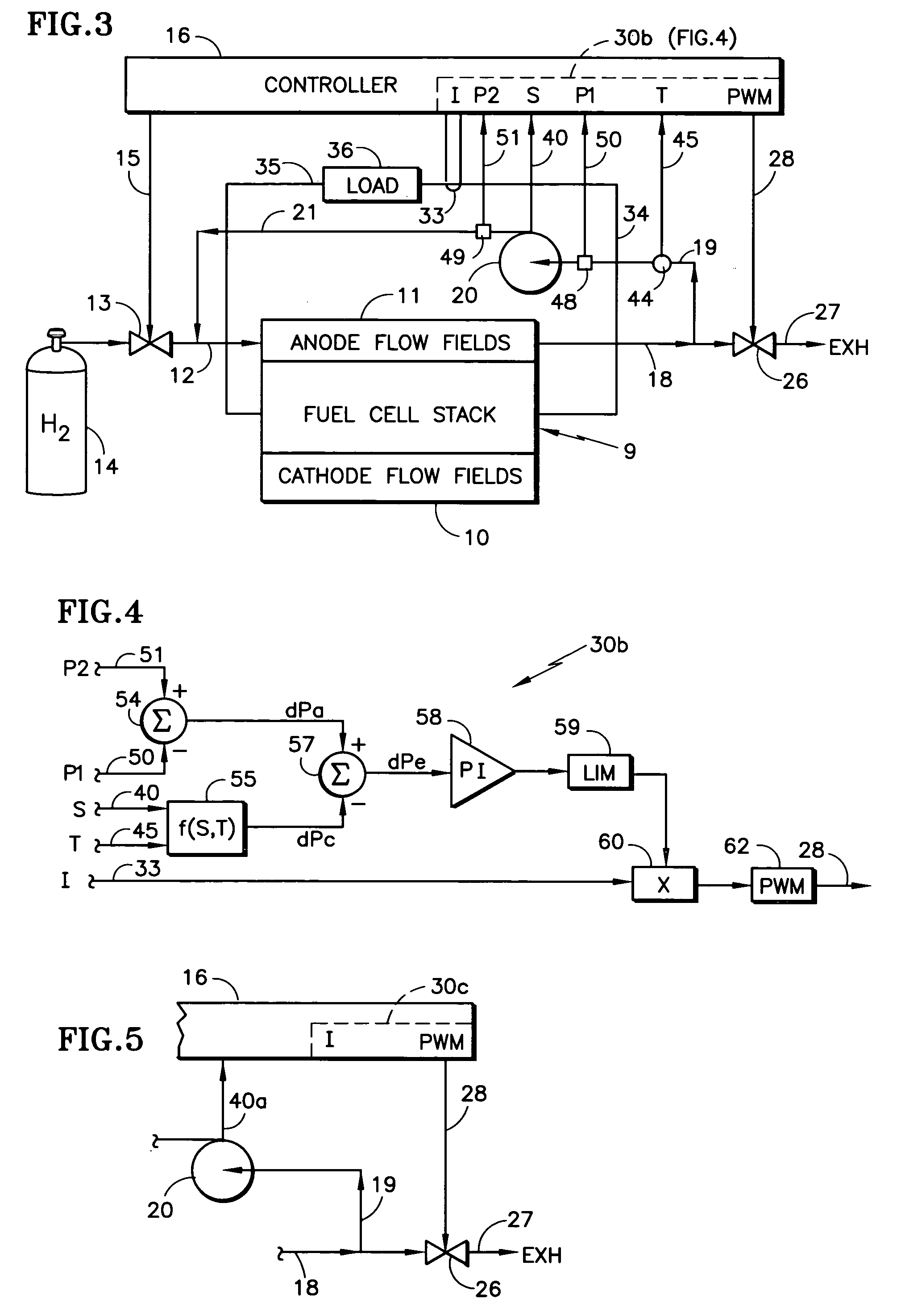
[0016] In order to control the amount of inert (non-fuel) gases in the anode flow fields 11, a purge valve 26 may periodically release small amounts of gas exiting the anode flow fields 11 to exhaust 27, which may be a suitably vented ambient or a burner, as is known. Control over the purge valve 26 may be in response to a pulse width modulation command on a signal line 28 from the controller 16 having a portion 30 that responds to current in the load to determine the...


PUM

PropertyMeasurementUnit
densityaaaaaaaaaa
speedaaaaaaaaaa
currentaaaaaaaaaa

Abstract

A fuel cell power plant fuel purge valve (26) is controlled in response to a parameter (40, 40a) of a fuel recycle blower which is indicative (20) of the recycle fuel impelled thereby, either alone or together with load current (33), pressure rise of the blower (50, 51), and temperature of the fuel recycle gas (44), to provide a pulse width modulation-control signal (28) controlling the purge valve.

Description

TECHNICAL FIELD [0001] This invention relates to monitoring the operating conditions of a fuel cell recycle fuel blower, such as speed or current, to estimate the ratio of hydrogen to non-hydrogen gases in the recycle stream, thereby to control a fuel purge valve. BACKGROUND [0002] It is well known that fuel cell power plants cannot be run at 100% fuel utilization, that is, providing the exact amount of fuel which is consumed in producing the desired electrical load, without resulting in fuel starvation at various regions of various fuel cells in the stack. Fuel cell starvation results in corrosion of the carbonaceous catalyst supports, resulting in reduced system power performance. To overcome this problem, recycling a portion of the fuel, which exits the anode fuel flow fields, to the inlets of the anode fuel flow fields provides overall fuel cell stack utilization of nearly 100%, while having a lower fuel cell utilization on a single pass, cell by cell basis. [0003] It is also kn...

Claims


Application Information

Patent Timeline
Patent Type & Authority Applications(United States)
IPC IPC(8): H01M8/04
CPCH01M8/04007Y02E60/50H01M8/04231H01M8/04097
Inventor CALLAHAN, CHRISTOPHER W.NARASIMHAMURTHY, PRAVEENMCCREADY, CHRISTOPHER P.
Owner INT FUEL CELLS
Why Eureka
Try Eureka