Vehicle front body structure

a front body and body technology, applied in the direction of roofs, jet propulsion mounting, transportation and packaging, etc., can solve the problems of crash energy not being properly transmitted to the vehicle upper portion, and the energy absorption of the front side frame with its axial compression cannot be properly achieved

Inactive Publication Date: 2007-09-20
MAZDA MOTOR CORP
View PDF12 Cites 66 Cited by
  • Summary
  • Abstract
  • Description
  • Claims
  • Application Information

AI Technical Summary

Benefits of technology

[0007]An object of the present invention is to provide a vehicle front body structure that can attain a proper energy absorption of the front side frame with its axial compression at a vehicle crash.

Problems solved by technology

As a result, there is a concern that an energy absorption of the front side frame with its axial compression could not be properly attained.
Thus, there is a concern the crash energy could not be properly transmitted to the vehicle upper portion.

Method used


Image

  • Vehicle front body structure
  • Vehicle front body structure
  • Vehicle front body structure

Examples


Embodiment Construction

[0043]Hereinafter, preferred embodiments will be described referring to the accompanying drawings.

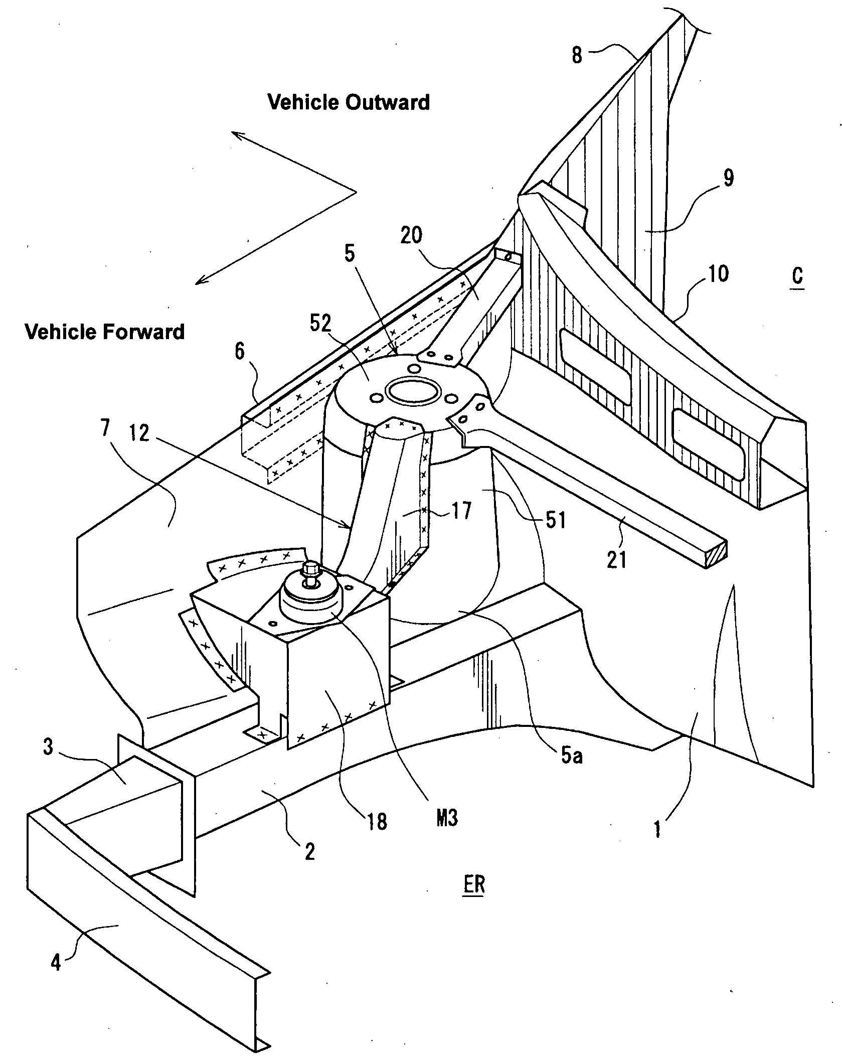
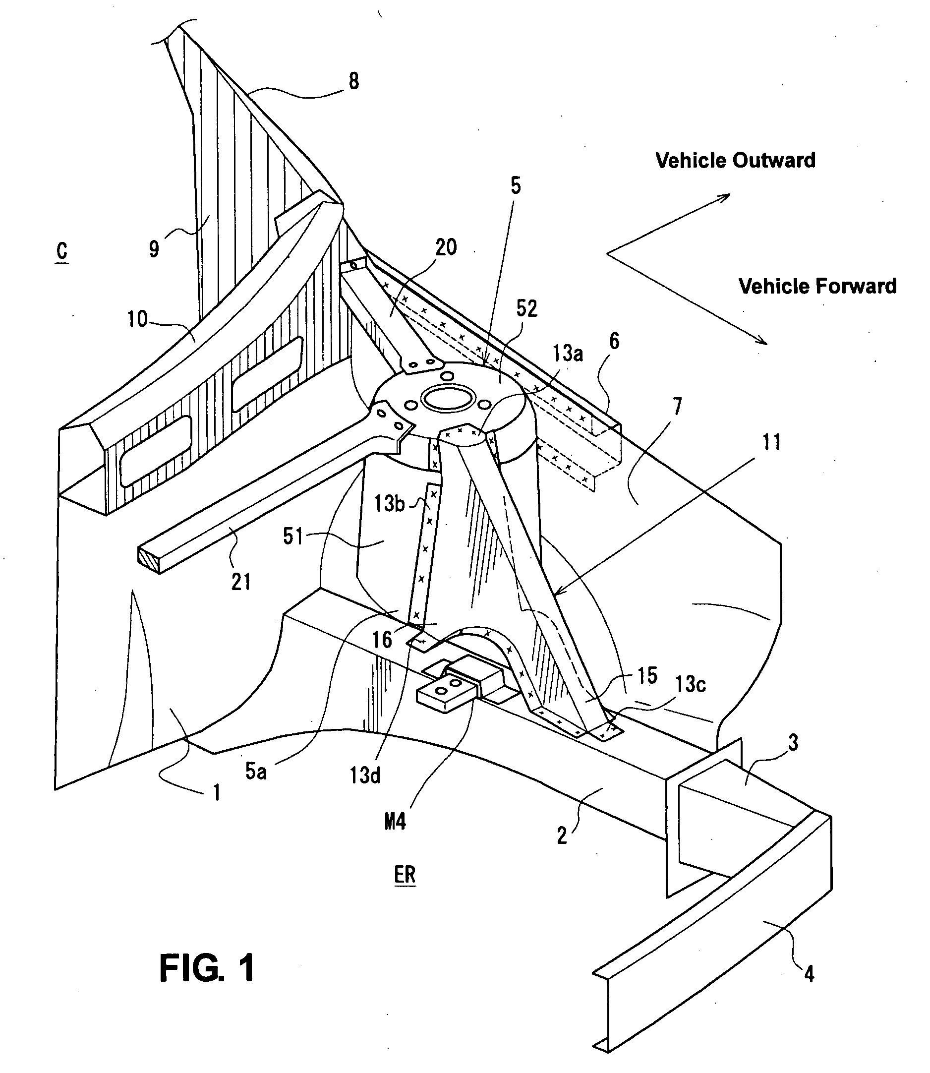
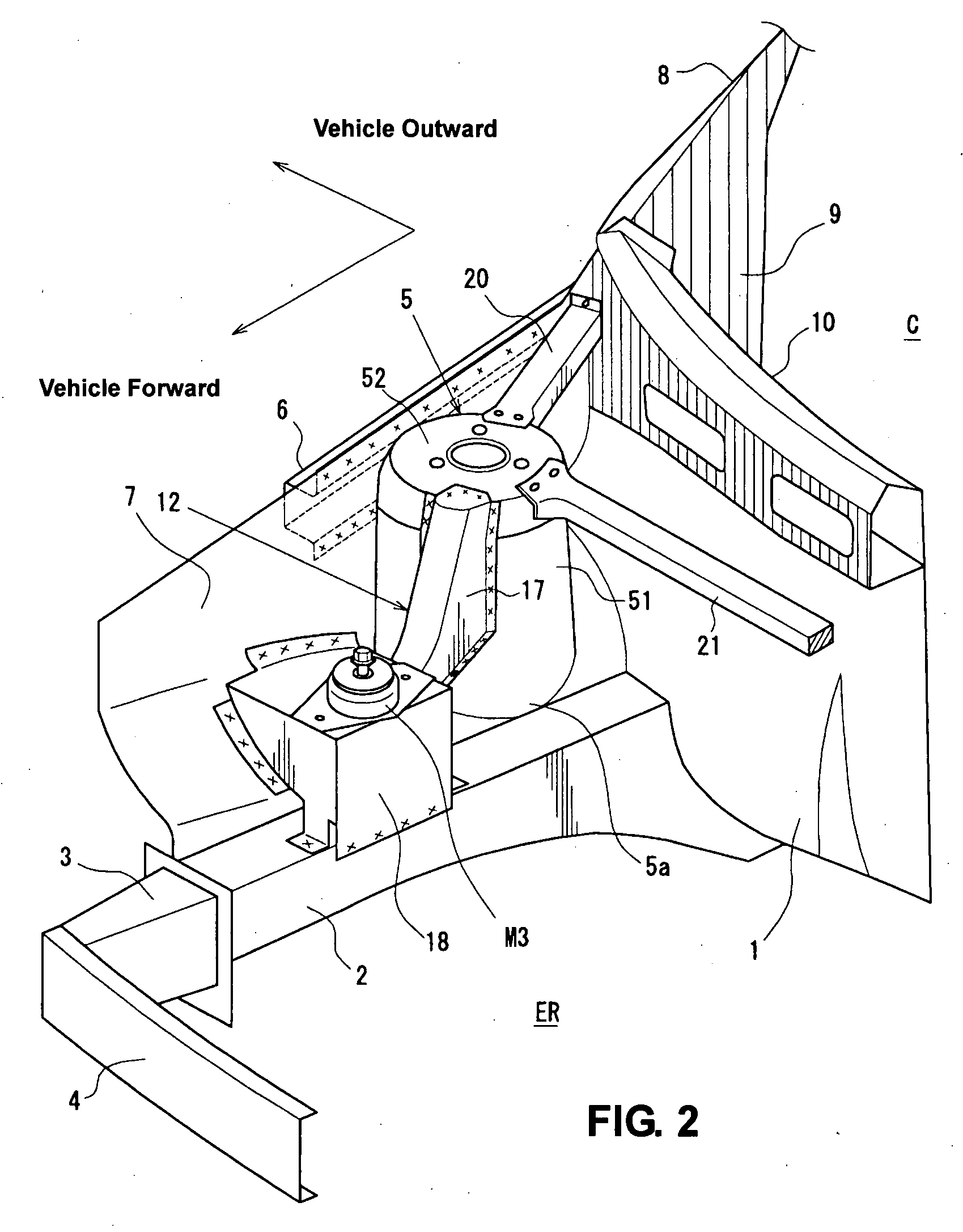
[0044]First, a first embodiment of the present invention will be described. FIG. 1 is a right-side perspective view showing a left-side portion of a vehicle front body structure of a first embodiment of the present invention. FIG. 2 is a left-side perspective view showing a right-side portion of the vehicle front body structure of the first embodiment of the present invention. FIG. 3 is an exploded perspective view of the left-side portion of the vehicle front body structure. FIG. 4 is a plan view of the vehicle front body structure. FIG. 5 is an elevation view of the left-side portion of the vehicle front body structure. FIG. 6 is a side view of the left-side portion of the vehicle front body structure, when viewed from an inside of an engine room. FIG. 7 is a sectional view taken along line A-A of FIG. 4. FIG. 8 is a sectional view taken along line B-B of FIG. 4. FIG. 9A is a sectiona...


PUM


Abstract

A bridge-shaped frame member is disposed on a front side frame in front of a suspension tower so as to extend vertically and stride over a No. 4 mount. Accordingly, there can be provided a vehicle front body structure that can attain a proper energy absorption of the front side frame with its axial compression can be attained at a vehicle crash.

Description

BACKGROUND OF THE INVENTION[0001]The present invention relates to a vehicle front body structure of an automotive vehicle, and in particular, relates to a vehicle front body structure that comprises a pair of right-and-left front side frames and suspension tower portions to accommodate a suspension device.[0002]Developments of properly transmitting a crash load acting on a front side frame extending in a longitudinal direction to a vehicle rear portion have been conducted for a vehicle front body structure of an automotive vehicle in order to improve a safety against a vehicle crash.[0003]In a conventional structure, the impact load is mainly transmitted to a body frame that is connected to a rear end of the front side frame and located at a vehicle lower portion. Herein, the impact load is not transmitted to a vehicle upper portion, so the front side frame may bend upward at its base portion near a dash panel. As a result, there is a concern that an energy absorption of the front s...

Claims


Application Information

Patent Timeline
Patent Type & Authority Applications(United States)
IPC IPC(8): B60K5/00B60J7/00
CPCB62D21/152B62D29/008B62D25/088
Inventor SASAKI, SHININOUE, MINORUAONUMA, TAKAHIROFUJII, HIROAKI
Owner MAZDA MOTOR CORP
Why Eureka
Try Eureka