
Hydrocyclone oil/sand/water separating apparatus

Inactive Publication Date: 2007-09-20
KAMPFER HANS PETER
View PDF6 Cites 15 Cited by
  • Summary
  • Abstract
  • Description
  • Claims
  • Application Information

AI Technical Summary

Benefits of technology

[0007] Another object is the provision of such an improved hydrocyclone separating apparatus which overcomes the above-given di

Problems solved by technology

The layer of wear-resistant low-friction material makes it very difficult for particles to deposit on the outer surfaces of the hydrocyclones.
Only over an extremely long time wi

Method used


Image

  • Hydrocyclone oil/sand/water separating apparatus
  • Hydrocyclone oil/sand/water separating apparatus

Examples


Example

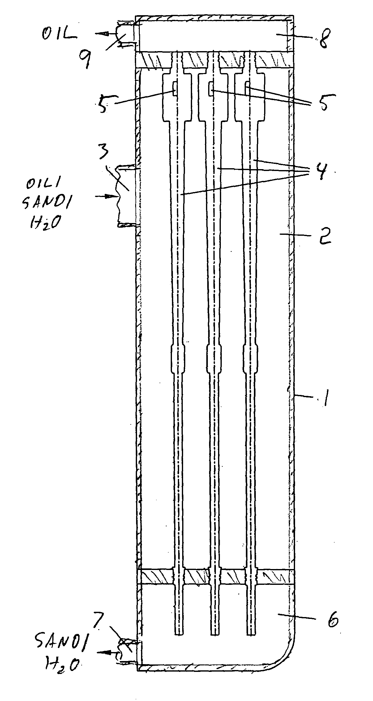
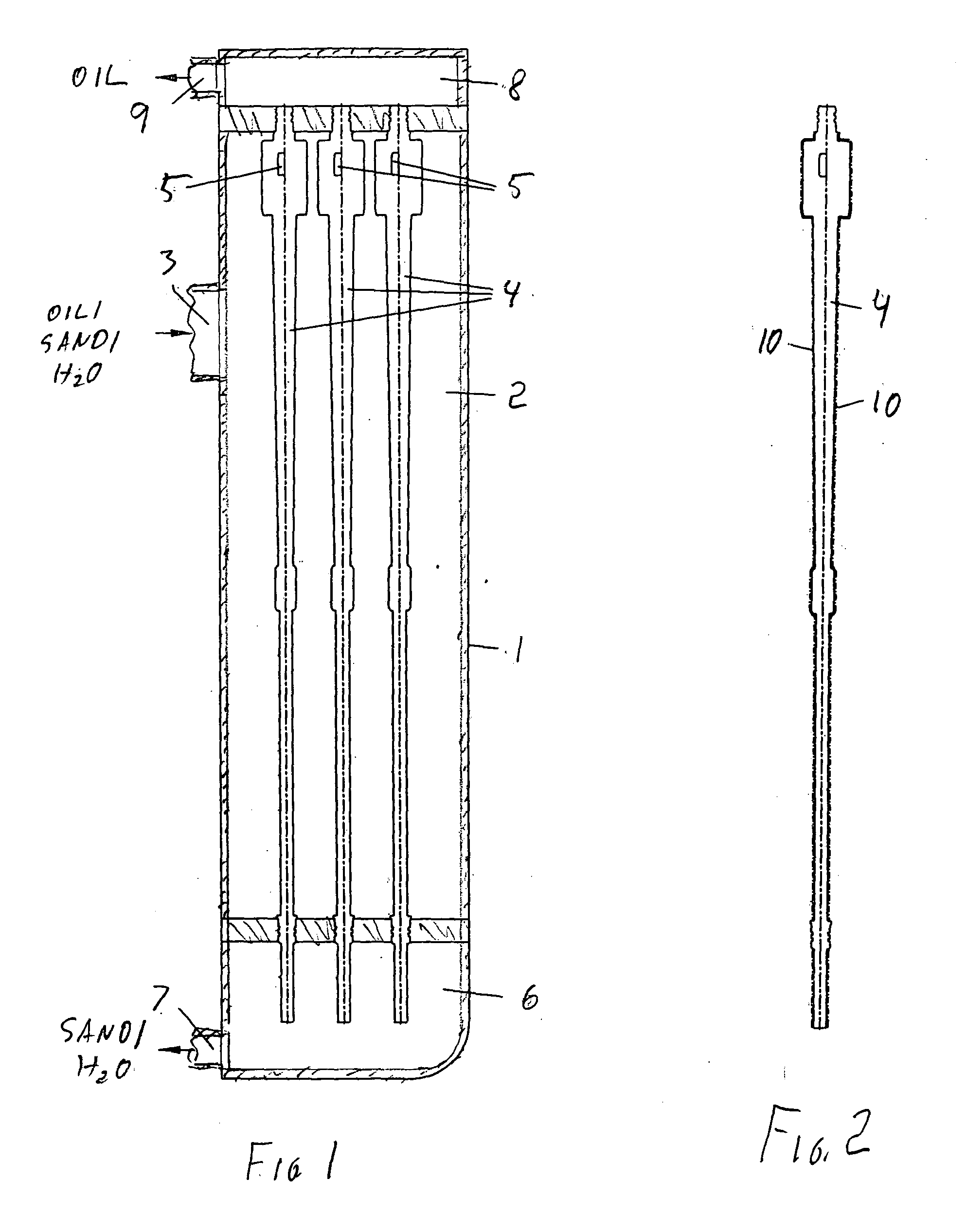
[0016] As seen in FIG. 1 a separating apparatus in accordance with the invention has a housing 1 defining a central input chamber 2 having an input port 3 for an oil / sand / water slurry, a lower end chamber 6 with an outlet port 7 for sand and water, and an upper end chamber 8 with an outlet port 9 for oil. Individual basically tubular and downwardly tapering hydrocyclones 4 have upper ends opening into the chamber 8 and lower ends opening into the chamber 6. At the upper region of the chamber 2, the wide upper ends of the hydrocyclones 4 have tangentially directed intakes 5. The system could of course also be operated with the hydrocyclones 4 horizontal.

[0017] Thus with this system the oil / sand / water slurry is pumped into the inlet port 3 so as to fill and pressurize the central chamber 2 around the hydrocyclones 4. This slurry enters the hydrocyclones 4 in the upper end of the chamber 2 via the intakes 5 that ensure cyclonic flow and separation inside the individual hydrocyclones 4...


PUM

PropertyMeasurementUnit
Thicknessaaaaaaaaaa
Thicknessaaaaaaaaaa
Durabilityaaaaaaaaaa

Abstract

A hydrocyclone separating apparatus has a housing subdivided into a central chamber provided with an input port and a pair of end chambers having respective outlet ports. A plurality of hydrocyclones extend across the central chamber between the end chambers. The hydrocyclones each have an intake in the central chamber and an end output in each of the output chambers. A fluent mixture pumped via the input port into the central chamber is separated by the hydrocyclones into a light fraction exiting one of the end chambers from the respective outlet port and a heavy fraction exiting the other of the end chambers from the respective outlet port. A layer of low-friction durable material such as polytetrafluoroethylene is provided on outer surfaces of the hydrocyclones in the central chamber.

Description

FIELD OF THE INVENTION[0001] The present invention relates to a separating apparatus. More particularly this invention concerns a separating apparatus having a plurality of hydrocyclones serving, for instance, for separating oil, sand, and water in an offshore drilling operation. BACKGROUND OF THE INVENTION [0002] A typical hydrocyclone separating apparatus as described in U.S. Pat. No. 5,667,687 of Lange has a housing subdivided into a central chamber provided with an input port and a pair of end chambers having respective outlet ports. A plurality of hydrocyclones as described in U.S. Pat. No. 3,724,674 is of Loison and U.S. Pat. No. 3,988,239 of Malina as well as in British patent document 2,214,841 of Hill extend across the central chamber between the end chambers. These hydrocyclones each have an intake in the central chamber and an end output in each of the output chambers. [0003] In such an apparatus a fluent mixture, e.g. a sand / oil / water slurry, pumped via the input port in...

Claims


Application Information

Patent Timeline
IPC IPC(8): B01D21/26B04C5/08B04C5/085B04C5/14
CPCB04C5/08B04C5/14B04C5/085
Inventor KAMPFER, HANS-PETER
Owner KAMPFER HANS PETER
Features
  • Generate Ideas
  • Intellectual Property
  • Life Sciences
  • Materials
  • Tech Scout
  • Unparalleled Data Quality
  • Higher Quality Content
  • 60% Fewer Hallucinations
Learn More