Friction stir welding process to join two or more members in forming a three-dimensional joint

a three-dimensional joint and friction stir technology, applied in welding/soldering/cutting articles, non-electric welding apparatus, manufacturing tools, etc., can solve the problems of difficult quality control, difficult installation of fasteners, and difficult etc., to facilitate the setup and alignment process, enhance the coupling effect, and reduce the number of members

Inactive Publication Date: 2007-09-20
LOCKHEED MARTIN CORP
View PDF4 Cites 26 Cited by
  • Summary
  • Abstract
  • Description
  • Claims
  • Application Information

AI Technical Summary

Benefits of technology

[0011] Additional embodiments may place an adhesive or barrier material that may both assist in fitting the first structural member to the second structural member prior to the friction stir weld as well as providing a barrier as the adhesive or barrier material is extruded into interface cavities at the friction stir weld joint. This method is particularly useful for structures where weight is a concern, such as an aircraft using aluminum or aluminum alloy structural members. By eliminating the need reinforce structural components due to the coupling of structural members using traditional fastener methods, the weight associated with these structural; members may be greatly reduced.
[0012] Another embodiment of the present invention provides a similar method for joining structural members. Again the first structural member is aligned and fitted to a second structural member wherein a channel within the first structural member receives a portion of the second structural member. In addition to this channel which may be used to fit the first structural member to the second structural member a male connector within either the first structural member and / or second structural member may be received within a female receptacle of the second structural member and / or first structural member. This may further facilitate the setup and alignment process. The materials of the male connector and female receptacle may be friction stir welded at the interface to further enhance the joint coupling the first structural member to the second structural member. Additionally, adhesive or barrier material may be placed at the channel, male connector, and / or female receptacle to assist in fitting and preventing contaminants from entering or penetrating the interface cavities that remain after joining the structural members.

Problems solved by technology

Structures constructed via bolted and fastened I-beams and C-beams often have problems translating stiffness and loads with minimal weight due to moment continuity.
Such holes often produce localized stresses and mechanical loads that the beams must account for.
Additionally, set up, tooling and the time required to drill holes may become major drivers in manufacturing as well as issues in quality assurance.
The installation of fasteners is also a process prone to quality assurance issues.
However, smaller complex three dimensional structures, such as aircraft designs, have not been easily addressed by the application of FSW.
Joining and properly plasticizing three-dimensional surfaces is difficult.
Thus it has been difficult to apply FSW processing to complex three-dimensional structures.
There are problems associated with each of these joining methods.

Method used


Image

  • Friction stir welding process to join two or more members in forming a three-dimensional joint
  • Friction stir welding process to join two or more members in forming a three-dimensional joint
  • Friction stir welding process to join two or more members in forming a three-dimensional joint

Examples


Embodiment Construction

[0021] Embodiments of the present invention are illustrated in the FIGUREs, like numerals being used to refer to like and corresponding parts of the various drawings.

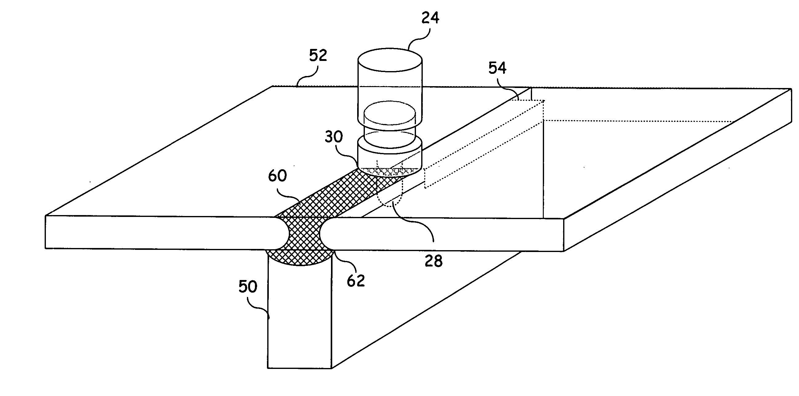
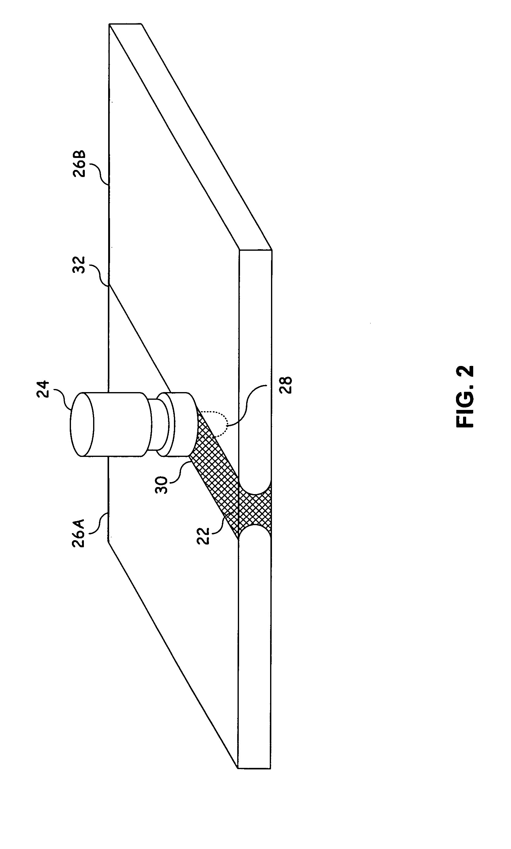
[0022] The present invention provides a means of joining a first structural member and a second structural member that substantially addresses the above identified needs. The first structural member is joined to a second structural member to form a three dimensional joint. This involves first aligning a first structural member to a second structural member. The first structural member has a channel with which to receive a portion of the second structural member. Once aligned, the first structural member and second structural member may be friction stir welded at the channel to plasticize the material adjacent to the channel of both the first structural member and the second structural member to form a friction stir weld joint. This allows three dimensional objects to be formed from the friction stir weld joined members...


PUM

PropertyMeasurementUnit
stiffnessaaaaaaaaaa
weightaaaaaaaaaa
timeaaaaaaaaaa

Abstract

A three dimensional joint is formed by coupling (joining) a first structural member and a second structural member. This involves first aligning a first structural member to a second structural member. The first structural member has a channel with which to receive a portion of the second structural member. Once aligned, the first structural member and second structural member may be friction stir welded at the channel to plasticize the material adjacent to the channel of both the first structural member and the second structural member to form a friction stir weld joint. This allows three dimensional objects to be formed from the friction stir weld joined members as opposed to merely allowing the joining of flat two dimensional surfaces.

Description

TECHNICAL FIELD OF THE INVENTION [0001] The present invention relates generally to structural joints and more particularly a method to join two or more members in forming a three-dimensional joint. BACKGROUND OF THE INVENTION [0002] Structural beams translate stiffness and other mechanical loads within structures such as buildings, vehicles, and bridges, etc. In one example, structural beams may be used to translate loads associated with the wing of an aircraft. These structural beams may include box beams, I-beams, double I-beams, C-Beams or other like structures that are efficient load carrying members. FIGS. 1A and 1B provide a cross section of a typical I-Beam and C-Beam. Such beams may be used in a variety of applications. I-Beams may be used for long clear spans requiring heavy loads. While C-Beams can be used where design and load requirements allow use of a C-Beam as opposed to an I-Beam, which provides additional support. Additionally a C-Beam may provide one flush surface ...

Claims


Application Information

Patent Timeline
Patent Type & Authority Applications(United States)
IPC IPC(8): B23K20/12
CPCB23K20/122B23K2203/10B23K2201/28B23K20/128B23K2101/28B23K2103/10
Inventor BARNES, JOHN E.
Owner LOCKHEED MARTIN CORP
Why Eureka
Try Eureka