Light-emitting device and a lens thereof

a technology of light-emitting devices and lenses, which is applied in the direction of instruments, lighting and heating apparatus, optical elements, etc., can solve the problems of difficult mold release, difficult mold design, and difficult mold release,

Inactive Publication Date: 2007-09-20
BRIGHT LED ELECTRONICS CORP
View PDF20 Cites 27 Cited by
  • Summary
  • Abstract
  • Description
  • Claims
  • Application Information

AI Technical Summary

Benefits of technology

[0012]According to yet another aspect of the present invention, there is provided a light-emitting device that includes a base, a light-emitting component, and a lens. The light-emitting component is mounted on the base. The lens directs light emitted by the light-emitting component sideways. The lens includes a lens body that has a bottom surface, a reflective surface, and a refractive surface. The bottom surface is disposed proximate to the light-emitting component. The reflective surface is disposed opposite to the bottom surface along a lens axis, and reflects a first portion of the light provided by the lig...

Problems solved by technology

However, because the shape of the lens is complicated (i.e., including a sawtooth surface), not only is mold design difficult, but mold release is also hard to perform.
In addition to the high cost attributed to fabrication of the mold, manufacturing of the lens is complex and tedious, and is especially difficult when high precision is required.
In addition, although the lens is used to direct light sid...

Method used


Image

  • Light-emitting device and a lens thereof
  • Light-emitting device and a lens thereof
  • Light-emitting device and a lens thereof

Examples


Embodiment Construction

[0029]Before the present invention is described in greater detail, it should be noted herein that like elements are denoted by the same reference numerals throughout the disclosure.

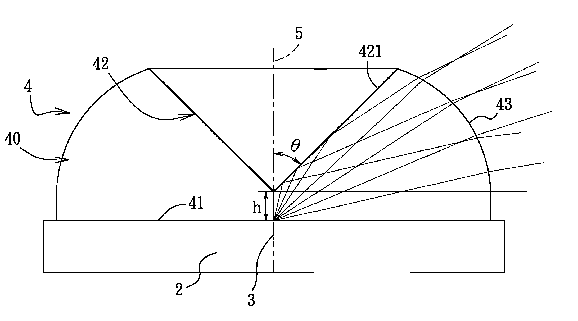
[0030]As shown in FIG. 3, the first preferred embodiment of a light-emitting device according to the present invention includes a base 2, a semiconductor light-emitting component 3, and a lens 4. The light-emitting component 3 is mounted on the base 2 and is disposed below the lens 4, i.e., the light-emitting component 3 is disposed between the base 2 and the lens 4. The light-emitting device has a central lens axis 5, and the light-emitting component 3 and the lens 4 are both symmetrical or substantially symmetrical about the central lens axis 5.

[0031]The base 2 is one that is commonly employed in conventional semiconductor light-emitting packages, and it can be but is not limited to a plastic coated metal support, an upright support, a planar support, or a piranha support. The light-emitting component 3...


PUM


Abstract

A lens includes a lens body having a bottom surface, a reflective surface, and a refractive surface. The bottom surface is to be disposed proximate to a light-emitting component. The reflective surface is disposed opposite to the bottom surface along a lens axis, and reflects a first portion of the light provided by the light-emitting component that is incident thereon toward the refractive surface. The refractive surface extends from an edge of the reflective surface to the bottom surface, and refracts a second portion of the light provided by the light-emitting component that is incident thereon as well as the first portion of the light reflected by the reflective surface theretoward in sideward directions relative to the light-emitting component. The lens body has cross-sections transverse to the lens axis, sizes of which increase gradually from a junction of the reflective surface and the refractive surface toward the bottom surface.

Description

CROSS-REFERENCE TO RELATED APPLICATION[0001]This application claims priority of Taiwanese Application No. 095108742, filed on Mar. 15, 2006.BACKGROUND OF THE INVENTION[0002]1. Field of the Invention[0003]The invention relates to a light-emitting device, more particularly to a light-emitting device and a lens thereof for directing light provided by a light-emitting component of the light-emitting device sideways.[0004]2. Description of the Related Art[0005]As shown in FIG. 1, U.S. Pat. No. 6,607,286 discloses a lens for directing light provided by a light-emitting diode 1 sideways. The lens includes a lens body that has a bottom surface 11, a total reflective surface 12, a first refractive surface 13, and a second refractive surface 14. The total reflective surface 12 has a funnel shape for reflecting a first portion of the light emitted by the light-emitting diode 1 and traveling through the bottom surface 11 (i.e., the portion of the light forming relatively small angles with a len...

Claims


Application Information

Patent Timeline
IPC IPC(8): F21V14/00
CPCH01L33/58H01L33/60G02B19/0061G02B19/0028G02B19/0071
Inventor CHEN, YEN-CHENGTSENG, CHING-LINCHEN, LIANG-TANGWANG, CHUNG-KAICHANG, MING-LI
Owner BRIGHT LED ELECTRONICS CORP
Why Eureka
Try Eureka