Encapsulation in a hermetic cavity of a microelectronic composite, particularly of a MEMS

Inactive Publication Date: 2007-09-20
COMMISSARIAT A LENERGIE ATOMIQUE ET AUX ENERGIES ALTERNATIVES
View PDF7 Cites 45 Cited by
  • Summary
  • Abstract
  • Description
  • Claims
  • Application Information

AI Technical Summary

Problems solved by technology

However, this option is relatively expensive, and limits the miniaturisation of assemblies.
The problem is that it is very difficult to obtain a very good vacuum or a controlled atmosphere in the cavity.
As the use of adhesion of the component forming the cover, conventionally using a polymer adhesive, involves very poor performances with respect to the hermeticity, other types of bonding have been developed.
However, the differential heat expansion between glass and silicon has an adverse effect on performances and rules out this technology for some MEMS.
However, this technology, which is difficult to control, applies significant constrai

Method used


Image

  • Encapsulation in a hermetic cavity of a microelectronic composite, particularly of a MEMS
  • Encapsulation in a hermetic cavity of a microelectronic composite, particularly of a MEMS
  • Encapsulation in a hermetic cavity of a microelectronic composite, particularly of a MEMS

Examples


Embodiment Construction

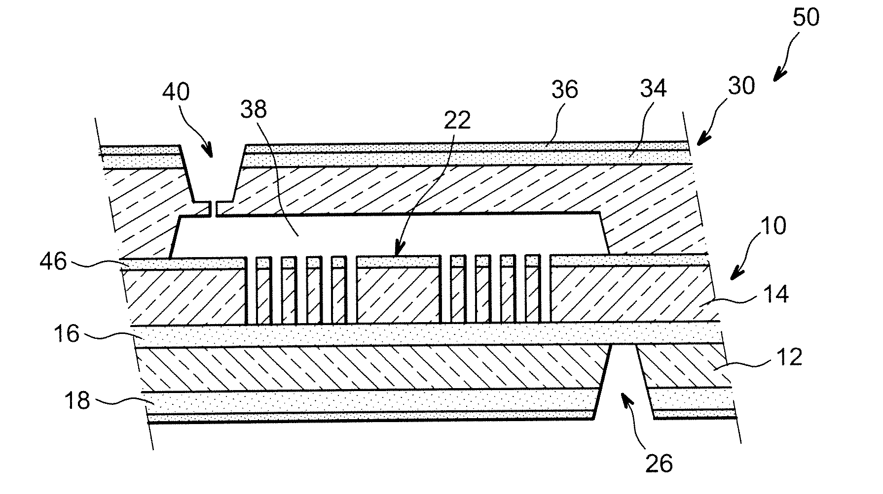
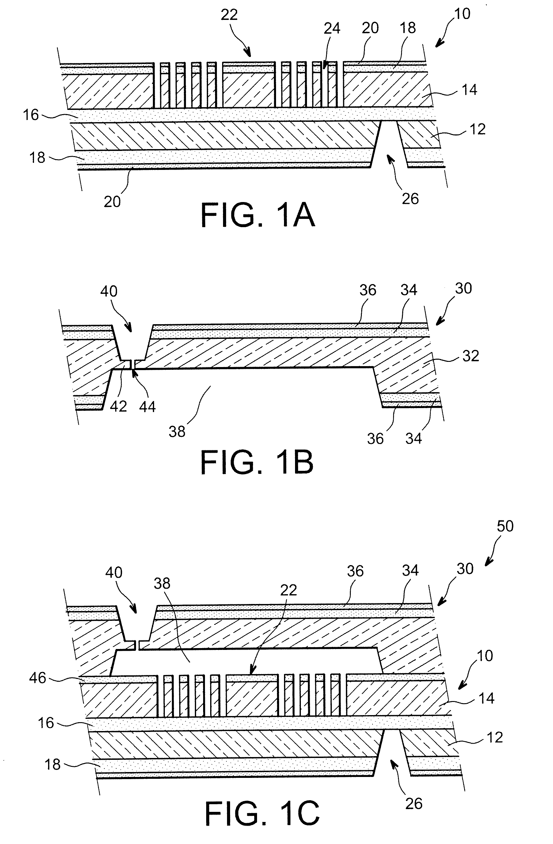
[0011]The invention proposes, among other advantages, to remedy the drawbacks of the existing technologies and use the direct bonding technique with wet surface preparation for composites comprising micro-electro-mechanical systems.

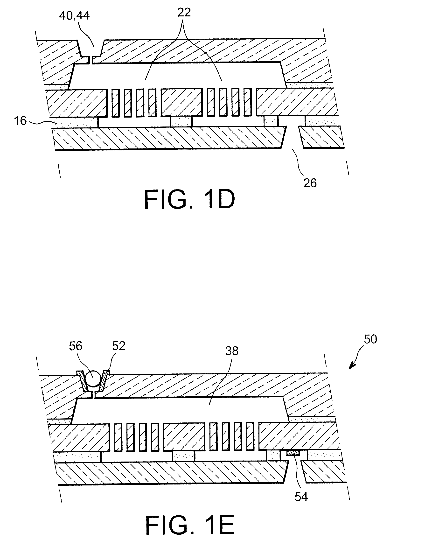
[0012]In fact, according to the invention, direct bonding is performed before the release of the MEMS structures: these structures remain attached to the substrate during the cover transfer by a sacrificial layer, particularly consisting of SiO2, which is removed after bonding by means of a vapour treatment, for example with hydrofluoric acid, preventing adhesions. The cavity is subsequently placed in a controlled atmosphere by filling the vents used for the release of the MEMS structure.

[0013]More generally, according to the invention, both constituent parts of the microelectronic composite, the cover and the substrate, respectively, are each prepared on their wafer of material, with formations of the cavity and slot of the MEMS structure to a sacrificia...


PUM


Abstract

To produce a structure of a micro-electro-mechanical system (MEMS) in a hermetic cavity (38) of a microelectronic device (50), a prepared cover (30) and substrate (10) are bonded by means of silicon direct bonding (SDB). To optimise the preparation of surfaces by means of wet cleaning without impairing the properties of the MEMS (22), i.e. without causing adhesions, the MEMS structure (22) is not released during bonding, but attached to the base (12) by means of a sacrificial intermediate layer (16). Said layer is removed once bonding has been carried out by injecting HF vapour via a vent (40) opening into the cavity (38).

Description

FIELD OF THE INVENTION[0001]The invention relates to the field of microdevices, particularly micro-electro-mechanical systems (or MEMS) which are isolated in hermetic cavities.[0002]The invention particularly relates to a method to produce such an MEMS enabling the use of controlled and inexpensive cavity bonding not impairing the performances of the components located therein.[0003]The invention also relates to characteristic intermediate devices according to the method.STATE OF THE RELATED ART[0004]Micro-electro-mechanical systems, actuators or sensors, are experiencing increasing development. In numerous cases, the active component is preferentially isolated in a hermetic cavity with respect to gas and moisture, so as to, for example, limit its ageing or increase measurement reliability. It may also be desirable to control the atmosphere inside the cavity, for example by means of a neutral gas making it possible to prevent any chemical reaction, or bond the cavity in a more or le...

Claims


Application Information

Patent Timeline
IPC IPC(8): H01L21/00
CPCB81C2203/0109B81C1/00285B81C1/00293B81C2203/0145
Inventor ROBERT, PHILIPPE
Owner COMMISSARIAT A LENERGIE ATOMIQUE ET AUX ENERGIES ALTERNATIVES
Why Eureka
Try Eureka