
Eureka
For R&D, Eureka makes reading and utilizing patents & technical documents easy.
Eureka AIR
Designed for self-driven R&D workflows. Generate viable solutions, solve complex R&D challenges, empower your innovation with AI.

Eureka Materials
Designed for material experts only. Revolutionize your material R&D, from search, analyze, to developing new materials.

TechResearch
Generate reliable direction feasibility study reports for your R&D in just a few steps.

TechSeek
Discover and master advanced knowledge NOW. Basics, ideas, possibilities, all at once.

TechMind
As an expert in R&D Theories, TechMind can generates customized viable solutions instantly.

TechRisk
Analyze your overall solution with one click, know your potential R&D risks in advance.

TechMonitor
Get weekly tech updates, stay abreast of the latest tech innovations and key insights.
Portable electronic device
- Summary
- Abstract
- Description
- Claims
- Application Information
AI Technical Summary
Benefits of technology
Problems solved by technology
Method used
Image

Examples
exemplary embodiment 1
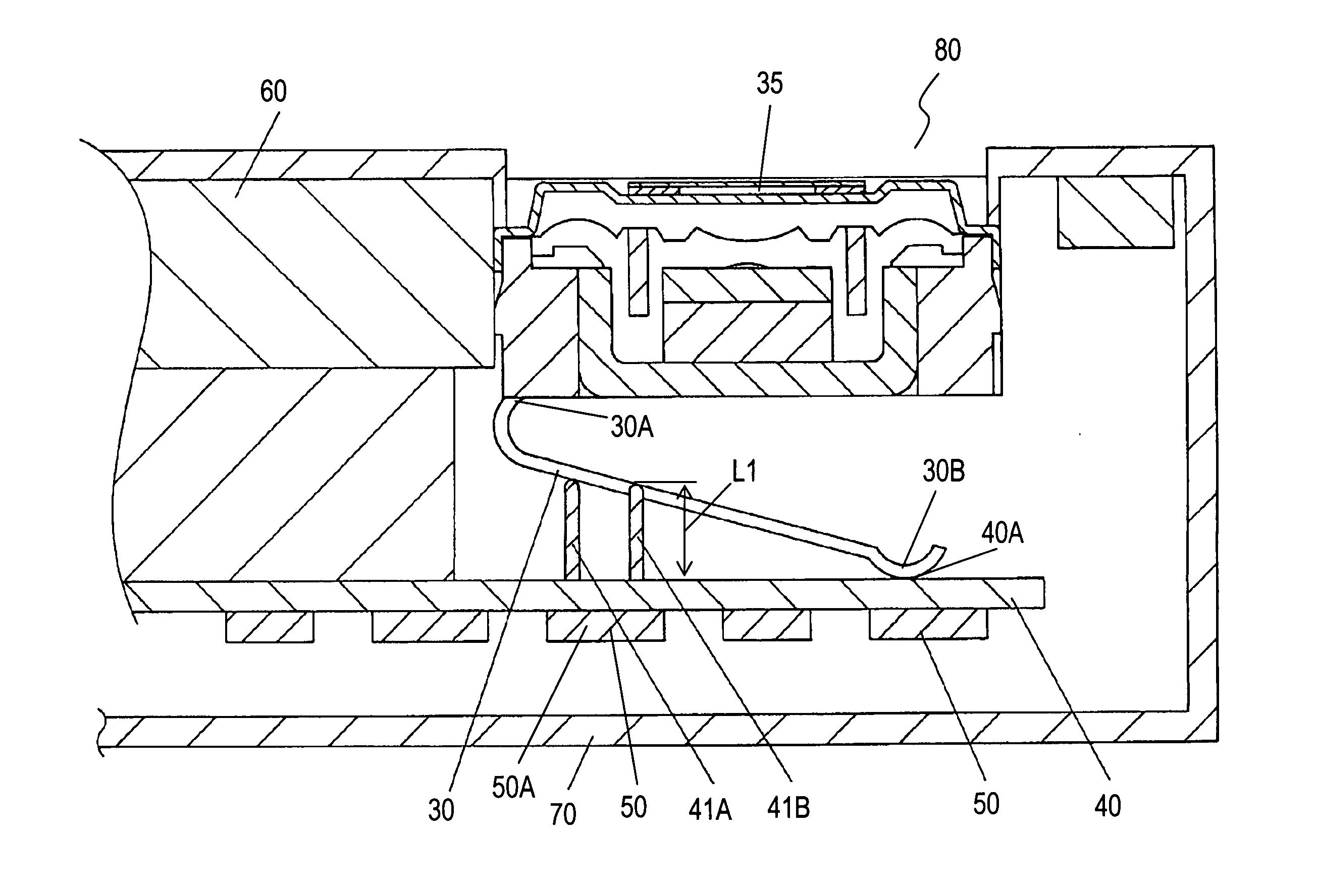
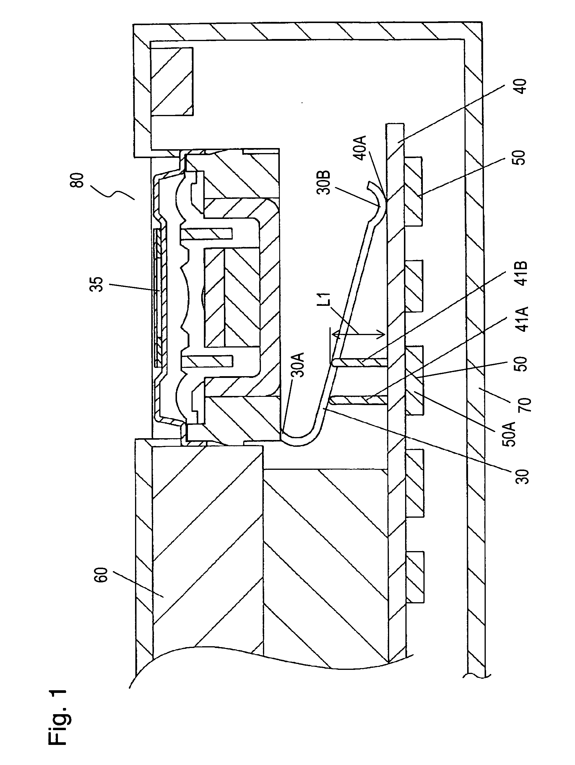
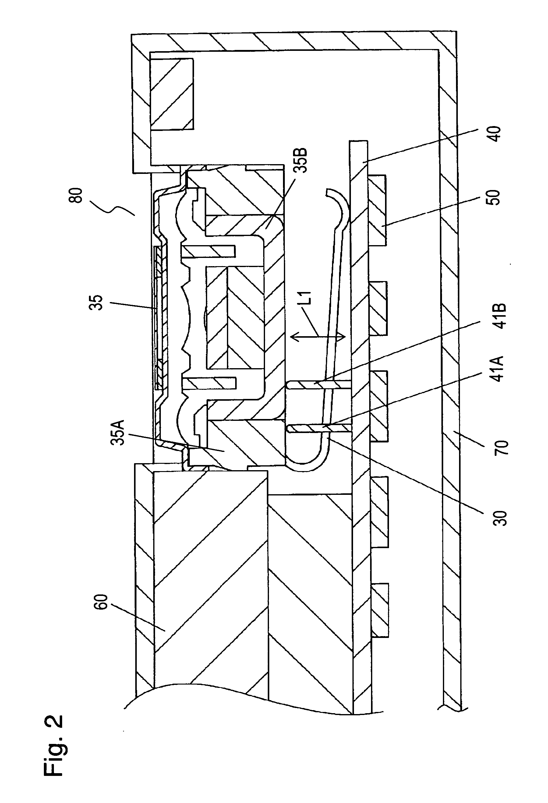
[0040]FIG. 1 and FIG. 2 are sectional views of portable phone 80, a portable electronic device in accordance with Exemplary Embodiment 1 of the present invention. Portable phone 80 includes loudspeaker 35 as an electronic component, circuit board 40 as a circuit component, display module 60, such as a liquid crystal display, and case 70 for accommodating them therein. Spring terminal 30 is formed by folding a single sheet-like elastic metal plate having conductivity. One end 30A of spring terminal 30 is connected to loudspeaker 35 and extends from loudspeaker 35. Upon receiving a pressure from circuit board 40, other end 30B of spring terminal 30 contacts circuit board 40. Loudspeaker 35 receives a power from power supply section 40A of circuit component 40 via spring terminal 30 to operate. When the pressure from circuit board 40 is eliminated, spring terminal 30 returns to its original shape due to its elasticity. However, when the distance between circuit board 40 and loudspeaker...
exemplary embodiment 2
[0053]FIG. 3 is a sectional view of portable phone 85, a portable electronic device in accordance with Exemplary Embodiment 2 of the present invention. In FIG. 3, elements similar to those of Embodiment 1 shown in FIG. 1 are denoted by the same reference numerals, and their description is omitted.
[0054] Stoppers 41C and 41D extend from circuit board 40, a circuit component, and are made of metallic material having pin shapes. Stoppers 41C and 41D are received by case 70, namely, a component other than electronic component (loudspeaker) 35, and component 51 other than loudspeaker 35 that is an electronic component, respectively. When loudspeaker 35, the electronic component including spring terminal 30, has insufficient resistance to impact, a component, such as case 70, having large resistance to impact and other components, are used as the receiving section for receiving stoppers 41C and 41D. This structure improves reliability and safety, accordingly improving the reliability and...
exemplary embodiment 3
[0055]FIG. 4 and FIG. 5 are sectional views of portable phone 180, a portable electronic device in accordance with Exemplary Embodiment 3 of the present invention. Portable phone 180 includes loudspeaker 135 as an electronic component, circuit board 140 as a circuit component, display module 160, such as a liquid crystal display, and case 170 for accommodating them therein. Spring terminal 130 is formed by folding a single sheet-like elastic metal plate having conductivity. One end 130A of spring terminal 130 is connected to loudspeaker 135 and extends from loudspeaker 135. Upon receiving a pressure from circuit board 140, other end 130B of spring terminal 130 contacts circuit board 140. Loudspeaker 135 receives a power from power supply section 140A of circuit component 140 via spring terminal 130 to operate. When the pressure from circuit board 140 is eliminated, spring terminal 130 returns to have its original shape due to its elasticity. However, when the distance between circui...
PUM
 Abstract
Description
Claims
Application Information
 - R&D Engineer
- R&D Manager
- IP Professional
- Industry Leading Data Capabilities
- Powerful AI technology
- Patent DNA Extraction
Browse by: Latest US Patents, China's latest patents, Technical Efficacy Thesaurus, Application Domain, Technology Topic, Popular Technical Reports.
© 2024 PatSnap. All rights reserved.Legal|Privacy policy|Modern Slavery Act Transparency Statement|Sitemap|About US| Contact US: help@patsnap.com