Simple folding box

a box and box body technology, applied in the field of simple folding boxes, can solve the problems of occupying a lot of space, low transportation efficiency, and boxes that are inclined to be crushed or stowed, and achieve the effect of reducing the bulk of products, efficient transportation and convenien

Inactive Publication Date: 2007-09-27
TAO JIAN
View PDF11 Cites 8 Cited by
  • Summary
  • Abstract
  • Description
  • Claims
  • Application Information

AI Technical Summary

Benefits of technology

[0005]This utility model has the following benefits: said two first side plates can be both connected to the lateral margin of said soleplate foldedly, so that said two first side plates can be folded to the same plane with that of said soleplate 1. Said second side plate can be connected to the lateral margin of said soleplate foldedly, and the connecting plate can be connected to said second side plate foldedly so that sa

Problems solved by technology

At present, the boxes used to place jewelries or leather shoes are usually paper boxes, which are usually connected together with drawing pins or rivets or pasted together with paper, thus,

Method used


Image

  • Simple folding box
  • Simple folding box
  • Simple folding box

Examples


first embodiment

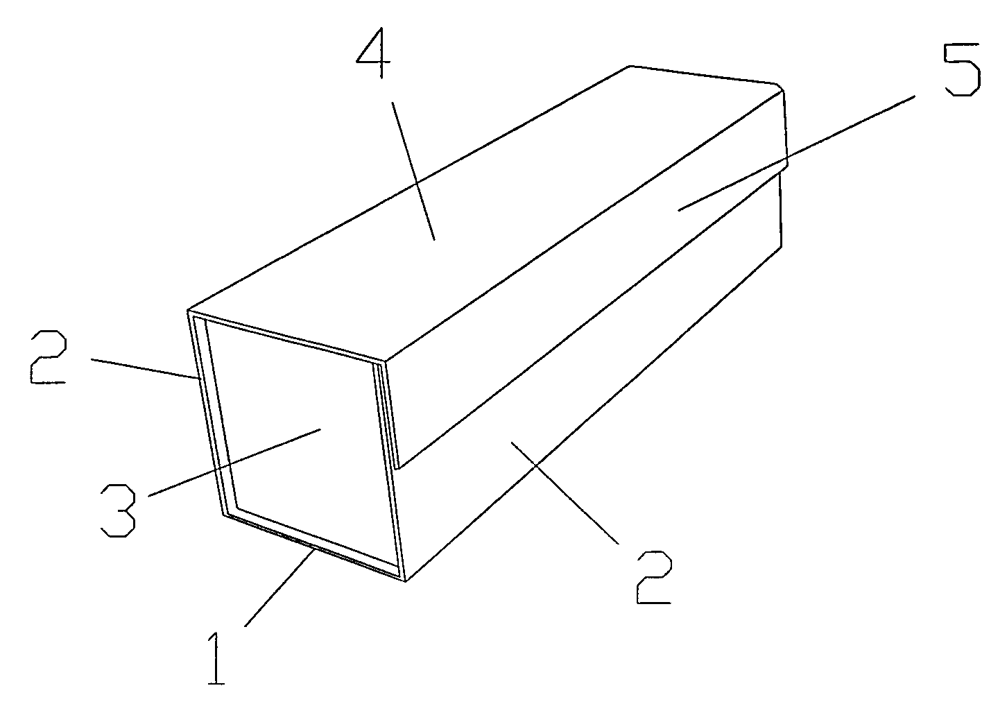
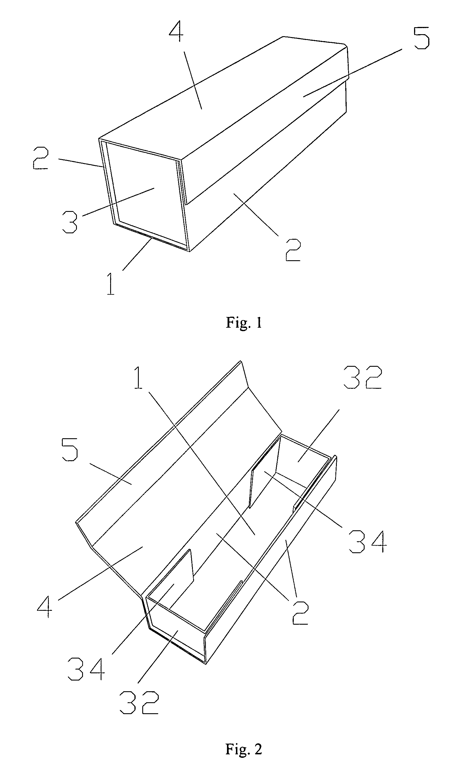
[0014]Referring to FIGS. 1 to 4, it is this kind of simple folding box, comprising a soleplate 1, two first side plate 2 which can be connected to a pair of opposite lateral margins of said soleplate foldedly, two U-shaped part 3, a cover plate 4 and a buckle plate 5.

[0015]Said soleplate 1 is a rectangle plate.

[0016]The hemlines of said two first side plate 2 are connected to a pair of opposite lateral margins of said soleplate 1 perpendicularly, and said two first side plates 2 is mounted on the upside of said soleplate 1.

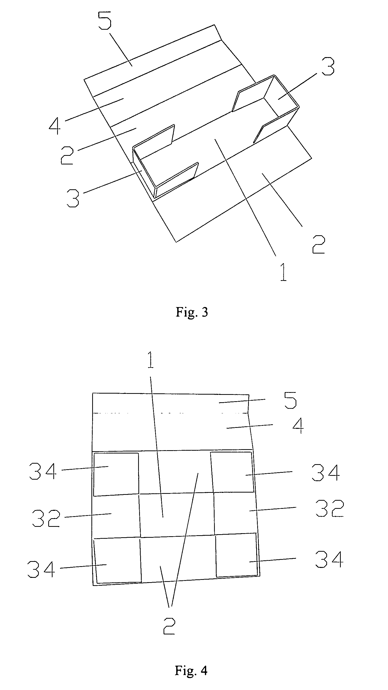
[0017]Each said U-shaped part 3 comprises a second side plate 32 which can be connected to said soleplate 1 foldedly and two connecting plate 34 which can be connected to a pair of opposite lateral margins of said second plate 32 foldedly.

[0018]The hemline of said second side plate 32 is connected to the other pair of lateral margins of said soleplate 1 perpendicularly, and said two second side plates 32 are mounted on the upside of said soleplate 1. The breadth o...

second embodiment

[0025]Referring to FIGS. 5 to 8, it is this kind of simple folding box, comprising a soleplate 1, two first side plate 2 which can be connected to a pair of opposite lateral margins of said soleplate 1 foldedly, two U-shaped part 3, and a cover plate 6.

[0026]Each said U-shaped part 3 comprises a second side plate 32 and two connecting plate 34.

[0027]Wherein said first side plate 2, two U-shaped part 3 are the same as those of the first embodiment.

[0028]Said soleplate 1, two first side plate 2, and two second side plate 32 enclose a cuboid box.

[0029]Said cover plate 6 comprises a board body 62 corresponding to said sole plate 1, and four sides of said board body 62 are prolonged a down to form a circle of edge 64. Said cover plate 6 is directly covered to said cuboid box.

[0030]The procedure of production is the same as that of first embodiment.

[0031]Said two first side plate 2 can be both connected to the lateral margin of said soleplate 1 foldedly, therefore, said two first side pla...


PUM


Abstract

A simple folding box, comprising a soleplate, two first side plates which can be connected to a pair of opposite lateral margins of said soleplate foldedly, two U-shaped parts; said soleplate is a rectangular plate, the hemlines of said two first side plates are connected to said soleplate perpendicularly; each said U-shaped part comprises a second side plate which can be connected to said soleplate foldedly and two connecting plates which can be connected to two opposite lateral margins of said second side plate foldedly; the hemline of said second side plate is connected to the other pair of opposite lateral margins perpendicularly; each said connecting plate is perpendicular to its corresponding second side plate, and there's gap between each said connecting plate and said soleplate; said two first side plates are connected to four connecting plates firmly; said soleplate, two first side plates, and two second side plates enclose a cuboid box.

Description

FIELD OF THE INVENTION[0001]This utility model relates to a kind of simple folding box, particularly relates to a kind of simple folding box that needs no worry of being crushed or staved in the transportation process and that makes the transportation convenient and efficient.BACKGROUND OF THE INVENTION[0002]At present, the boxes used to place jewelries or leather shoes are usually paper boxes, which are usually connected together with drawing pins or rivets or pasted together with paper, thus, the boxes can not stand crushing, and takes a lot of space in transportation process, accordingly, the transportation has low efficiency and the boxes are inclined to be crushed or staved,SUMMARY OF THE INVENTION[0003]The purpose of this utility model is to offer a kind of simple folding box, which needs no worry of being crushed or staved in transportation process and make the transportation convenient and efficient.[0004]To reach above-mentioned purpose, this utility model offers a kind of ...

Claims


Application Information

Patent Timeline
IPC IPC(8): B65D43/08B65D5/00
CPCB65D5/22B65D5/2076
Inventor TAO, JIAN
Owner TAO JIAN
Why Eureka
Try Eureka