Imaging apparatus with resolution adjustability

a technology of resolution adjustment and imaging apparatus, which is applied in the direction of instruments, television systems, and television system scanning details, etc., can solve the problems of increasing the resolution, affecting the accuracy of image resolution, and reducing so as to save the number of sensing assemblies and prevent the error between a sensed image and a to-be-sensed image

Inactive Publication Date: 2007-09-27
BENQ CORP
View PDF0 Cites 8 Cited by
  • Summary
  • Abstract
  • Description
  • Claims
  • Application Information

AI Technical Summary

Benefits of technology

[0010]The invention is directed to an imaging apparatus with resolution adjustability. The imaging apparatus with resolution adjustability in which prisms of a prism assembly moveable relative to each other are designed to guide an imaging beam to form an image within different areas of an image sensor. Therefore, the imaging apparatus can save the number of sensing assemblies and use a plane array sensor; meanwhile the error between a sensed image and a to-be-sensed image is prevented.

Problems solved by technology

Meanwhile, due to the manufacturing technology and cost, the increase in image resolution achieved by staggered sensing structure is certainly limited.
Therefore, an increase in resolution results in an error between the sensed image and the original to-be-sensed image.
Moreover, the plane array sensor cannot use the above staggered sensing structure to increase image resolution.

Method used


Image

  • Imaging apparatus with resolution adjustability
  • Imaging apparatus with resolution adjustability
  • Imaging apparatus with resolution adjustability

Examples


first embodiment

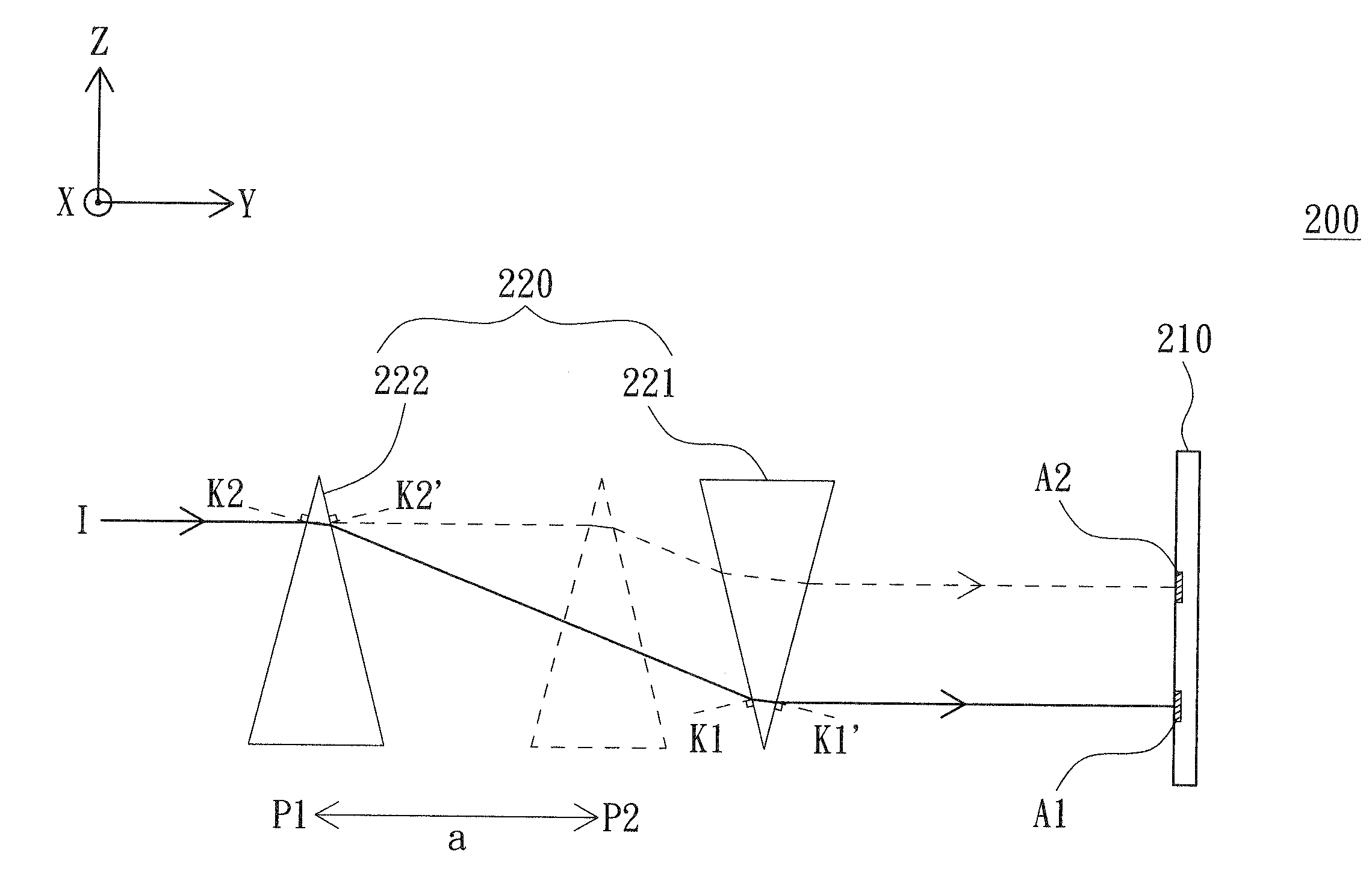
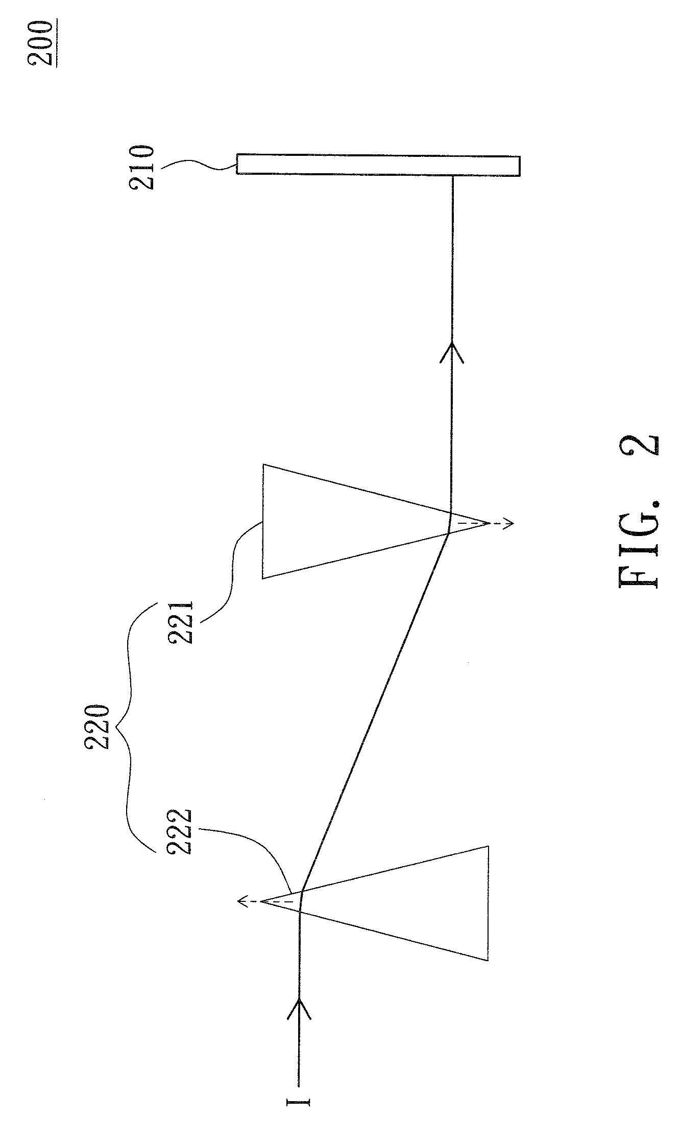
[0025]In the first embodiment, the image sensor 210 is exemplified by a line array sensor. Meanwhile, the imaging apparatus 200 can be used in an ordinary scanner. The imaging apparatus 200 further comprises a lens (such as a lens assembly) for focusing the imaging beam 1. The prism assembly 220 is disposed between the lens and the image sensor 210; or, the lens is disposed between the prism assembly 220 and the image sensor 210. In the first embodiment, the prism assembly 220 is disposed between the lens and the image sensor 210 to guide the imaging beam I focused by passing through the lens.

[0026]Referring to FIG. 3, a diagram showing relative movement between two prisms 221 and 222 according to a first embodiment of the invention is shown. In FIG. 3, the lens is not shown, and the +X axis is in the direction normal to the paper. As indicated in FIG. 3, the image sensor 210 is disposed along the direction of the Z axis, and the sensing area thereof is parallel to the X-Z plane and...

second embodiment

[0033]In the second embodiment, the image sensor 210 is exemplified by a plane array sensor. Meanwhile, the imaging apparatus 200 can be used in an ordinary digital camera comprising a lens (such as a lens assembly) for focusing the imaging beam 1. In the second embodiment, the prism assembly 220 is disposed between the lens and the image sensor 210.

[0034]Referring to FIG. 6, a diagram showing the relative movement between the prisms according to a second embodiment of the invention is shown. In FIG. 6, the directions of the X axis, the Y axis and the Z axis are the same with that in FIG. 3. Meanwhile, the direction of the Z axis is normal to the paper, and the sensing area of the image sensor is parallel to the X-Z plane and toward the direction of the −Y axis. Moreover, FIG. 6 differs from FIG. 3 in that the prism assembly 220 further comprises a third prism 223 and a fourth prism 224 as indicated in FIG. 6. Like the first prism 221 and the second prism 222, the third prism 223 an...


PUM


Abstract

An imaging apparatus with resolution adjustability is provided. The imaging apparatus comprises an image sensor and a prism assembly. The prism assembly guides the imaging beam to the image sensor. The prism assembly comprises a first prism and a second prism. The second prism moves between a first position and a second position relative to the first prism. The vertex angle direction of the first prism differs from that of the second prism by 180 degrees. As the second prism is in the first position relative to the first prism, the imaging beam forms an image within a first area of the image sensor through the first prism and the second prism. As the second prism is in the second position relative to the first prism, the imaging beam forms an image within a second area of the image sensor through the first and the second prism.

Description

[0001]This application claims the benefit of Taiwan application Serial No. 95110578, filed Mar. 27, 2006, the subject matter of which is incorporated herein by reference.BACKGROUND OF THE INVENTION[0002]1. Field of the Invention[0003]The invention relates in general to an imaging apparatus with resolution adjustability, and more particularly to an imaging apparatus with resolution adjustability in which prisms of a prism assembly moveable relative to each other are designed to guide an imaging beam to form an image within different areas of an image sensor.[0004]2. Description of the Related Art[0005]Ordinary image acquisition devices sense a light signal from a to-be-sensed image by a charge couple device (CCD) sensor first, converts the light signal into an image signal by a shift register, and then transmits the image signal to a subsequent analog signal processing circuit for further processing. T0 achieve the object of high resolution, an image sensor having a staggered sensing...

Claims


Application Information

Patent Timeline
Patent Type & Authority Applications(United States)
IPC IPC(8): H01L27/00
CPCH04N3/1587H04N25/48
Inventor CHEN, JUN
Owner BENQ CORP
Why Eureka
Try Eureka