Substrate support structure, heat treatment apparatus using same, first sheet-like object for use in the substrate support structure, method of manufacturing the substrate support structure, heat treatment apparatus, and substrate sucking method

Active Publication Date: 2007-09-27
DAINIPPON SCREEN MTG CO LTD
View PDF13 Cites 185 Cited by
  • Summary
  • Abstract
  • Description
  • Claims
  • Application Information

AI Technical Summary

Benefits of technology

[0053]According to this feature, there is no need to form

Problems solved by technology

This results in an inconvenience of a great difference in heat history over the subst

Method used


Image

  • Substrate support structure, heat treatment apparatus using same, first sheet-like object for use in the substrate support structure, method of manufacturing the substrate support structure, heat treatment apparatus, and substrate sucking method
  • Substrate support structure, heat treatment apparatus using same, first sheet-like object for use in the substrate support structure, method of manufacturing the substrate support structure, heat treatment apparatus, and substrate sucking method
  • Substrate support structure, heat treatment apparatus using same, first sheet-like object for use in the substrate support structure, method of manufacturing the substrate support structure, heat treatment apparatus, and substrate sucking method

Examples


embodiment 1

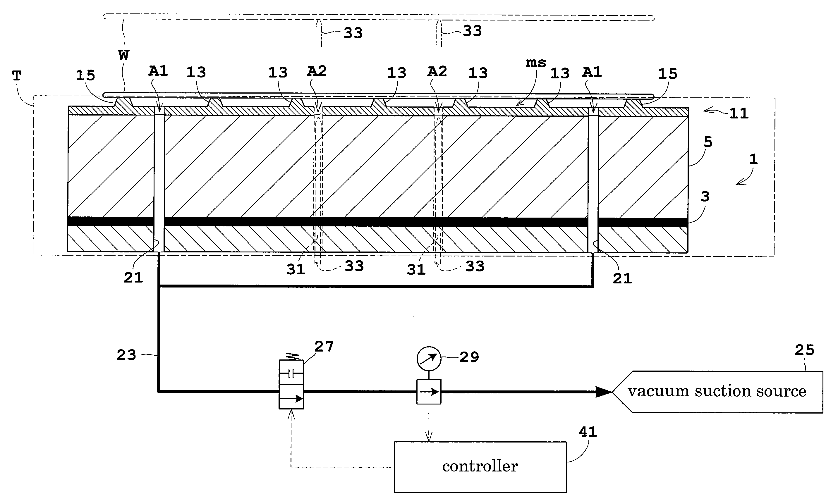
[0079]Embodiment 1 of this invention will be described hereinafter with reference to the drawings.

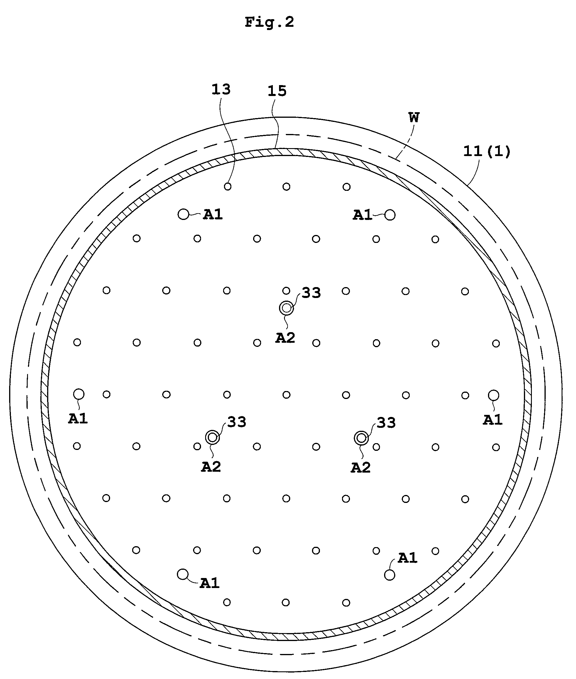
[0080]FIG. 1 is a view in vertical section showing an outline of a heat treatment apparatus in Embodiment 1. FIG. 2 is a plan view of a heat-treating plate.

[0081]A heat-treating plate 1 is circular and has a slightly larger diameter than a wafer W in plan view. The upper surface of the plate 1 is flat. The heat-treating plate 1 is formed of a metal such as copper or aluminum having high thermal conductivity, for example. The heat-treating plate 1 has a heating element 3 such as a mica heater mounted therein. A heat transfer portion 5 between the heating element 3 and the upper surface of heat-treating plate 1 has a plurality of heat pipes, not shown, embedded therein. Cooling grooves, not shown, are formed between the heat pipes for circulating a cooling fluid. The heat-treating plate 1 corresponds to the plate body in this invention. The heating element 3 corresponds to the heating dev...

embodiment 2

[0119]Embodiment 2 of this invention will be described hereinafter with reference to the drawings.

[0120]FIG. 7 is a view in vertical section showing an outline of a heat treatment apparatus in Embodiment 2. FIG. 8A is a plan view of a heat-treating plate. FIG. 8B is a fragmentary plan view of a support sheet.

[0121]A heat-treating plate 101 is circular and has a slightly larger diameter than a wafer W in plan view. The upper surface of the plate 101 is flat. The heat-treating plate 101 is formed of a metal such as copper or aluminum having high thermal conductivity, for example. The heat-treating plate 101 has a heating element 103 such as a mica heater mounted therein. A heat transfer portion 105 between the heating element 103 and the upper surface of heat-treating plate 101 has a plurality of heat pipes, not shown, embedded therein. Cooling grooves, not shown, are formed between the heat pipes for circulating a cooling fluid.

[0122]A support sheet 111 formed of resin is laid on the...

embodiment 3

[0150]Embodiment 3 of this invention will be described with reference to FIG. 12.

[0151]FIG. 12 is a view in vertical section showing an outline of a heat treatment apparatus in Embodiment 3. Parts identical to those of Embodiment 2 are shown with the same reference numerals, and will not be described again.

[0152]The heat treatment apparatus in Embodiment 3 is characterized in that guides 121 are mounted on the support sheet 111. That is, the support sheet 111 in Embodiment 3 has the projections 113, sealer 115 and fourth openings A4, but does not include the third openings A3 described in Embodiment 2.

[0153]The guides 121 are placed directly in predetermined positions on the support sheet 111. Preferably, the guides 121 are lightweight to the extent of permitting expansion and contraction of the support sheet 111. The guides 121 correspond to the guide elements (particularly the guide elements acting also as the weights) in this invention. When a predetermined heat treatment is carr...


PUM


Abstract

A heat treatment apparatus includes a support sheet placed on an upper surface of a heat-treating plate. The support sheet has, formed on an upper surface thereof, projections for contacting and supporting a substrate, and a lip for contacting edge regions of the substrate. The support sheet is formed by an etching process, and therefore areas of the sheet around the projections are recessed, rather than being perforated as in the case of laser processing. These heat-treating plate and support sheet constitute a substrate support structure capable of supporting the substrate properly.

Description

BACKGROUND OF THE INVENTION[0001](1) Field of the Invention[0002]This invention relates to a substrate support structure for supporting substrates such as semiconductor wafers, glass substrates for liquid crystal displays, glass substrates for photomasks and substrates for optical disks (hereinafter simply called “substrates”), a first sheet-like object for use in the substrate support structure, a method of manufacturing the substrate support structure, a heat treatment apparatus for heat-treating the substrates, and a substrate sucking method for sucking the substrates.[0003](2) Description of the Related Art[0004]As requirements for fine line width and line width uniformity of patterns formed on substrates have become increasingly stringent in recent years, a strong demand is being placed for temperature uniformity in baking treatment in photolithography, especially in baking treatment after exposure (PEB: Post Exposure Bake).[0005]Thus, a heat treatment apparatus has been propos...

Claims


Application Information

Patent Timeline
IPC IPC(8): B25B11/00
CPCB25B11/005H01L21/67103H01L21/6875H01L21/68735H01L21/68742H01L21/6838H01L21/00H01L21/02H01L21/324H01L21/477
Inventor FUKUMOTO, YASUHIROTSUJI, MASAOMIYAUCHI, HIROSHITANIGUCHI, HIDEYUKI
Owner DAINIPPON SCREEN MTG CO LTD
Why Eureka
Try Eureka