Reinforcement for a hose coupling

a technology of hose couplings and reinforcements, which is applied in the direction of hose connections, pipe connection arrangements, mechanical equipment, etc., can solve the problems of not protecting the inner sleeve of the coupling from deformation, heavy gauge steel adds unwanted cost and weight to the coupling assembly, and sealing does not in any way prevent the inner sleeve from deformation, so as to improve the integrity and long-term durability of the hose coupling, and prevent the inner sleev

Inactive Publication Date: 2007-09-27
HUTCHINSON FTS INC
View PDF7 Cites 16 Cited by
  • Summary
  • Abstract
  • Description
  • Claims
  • Application Information

AI Technical Summary

Benefits of technology

[0018] By analyzing failed couplings, where the inner sleeve has collapsed from crimp forces, the applicant can predict the exact area of the inner sleeve that will fail for each individual design. Accordingly, the reinforcing ring is strategically located concentric with the predicted area of failure to reinforce the inner sleeve during the crimping operation. The reinforcing ring resists the peak pressure from the crimping force and thus prevents damage to the inner sleeve from occurring, thereby improving the integrity and long-term durability of the hose coupling.
[0019] Prior art reinforcements are longer than necessary and therefore undergo beam deflection during the crimping operation. The reinforcing ring of the present invention provides more rigid reinforcement because it is discrete—strategically located only where absolutely necessary—and thereby undergoes virtually no beam deflection. Additionally, the reinforcing ring is smaller and lighter than prior art reinforcements and accordingly will be less expensive.
[0020] Accordingly, it is an object of the present invention to protect the inner sleeve of a tubular coupling from deforming under the pressure of the crimp force.
[0021] It is another object of the present invention to reinforce the area of peak crimp force of the tubular coupling during the crimping process to ensure integrity and long-term durability of the coupling.
[0022] It is yet another object of the present invention to provide a more rigid, lower cost, and lighter weight tubular coupling than is presently known in the art.
[0023] It is a further object of the present invention to provide a tubular coupling having an outer sleeve that is crimped, an inner sleeve, and at least one reinforcing ring inside the inner sleeve located in the same plane as the area of peak crimp force of the coupling so as to increase the overall life of the crimped connection.

Problems solved by technology

Unfortunately, heavy gauge steel adds unwanted cost and weight to the coupling assembly.
While the sealing members provide a seal to prevent leaks, they do not add any structural benefit to the fitting, nor do they protect the inner coupling member from forces applied to crimp the coupling to the hose.
Therefore, coupling and use of the split ring to enhance sealing does not in any way prevent the inner sleeve of the coupling from deformation in case of an excessive crimping force.
The placement of the ring prevents expansion of the inner rubber portion of the hose over the strengthening ring and compression of the rubber hose between the ring and the coupling sleeve, that causes damage to the hose and speeds deterioration and failure of the hose and coupling connection.
Therefore, the strengthening ring may reinforce the hose, but does not necessarily protect the inner sleeve of the coupling from excessive crimping forces.
In other words, while the tubular liner of Joseph et al. may add strength, it also adds significantly more weight and cost.
Another problem with the relatively long tubular insert of Joseph et al. is one of beam deflection.
Under radial compression, the relatively long tubular liner is weaker and more prone to deflection than a more discrete element of the same cross section would be.
That is, when the crimping force is applied to the coupling, the relatively long tubular liner will have a tendency to compress relatively easily because of cumulative deflection along the length of the tubular liner.
Additionally, in an automotive air-conditioning system, the flow of fluid, such as refrigerant fluid, should not be disrupted or it may adversely affect the operation of the air-conditioning system.
Accordingly, a disadvantage of the tubular liner disclosed by Joseph et al. is that the reduced inner diameter of the coupling over the entire length of the tubular liner results in a significantly restricted flow of fluid through the coupling.
Further, in a vehicle's air-conditioning system, hose couplings are exposed to a harsh environment where the hose couplings are damaged due to heat and vibrations generated by the vehicle's engine.
The harsh engine environment coupled with increased pressure on the hose couplings at the deformed crimped connections has been known to cause prior art couplings to fail prematurely.

Method used


Image

  • Reinforcement for a hose coupling
  • Reinforcement for a hose coupling
  • Reinforcement for a hose coupling

Examples


Embodiment Construction

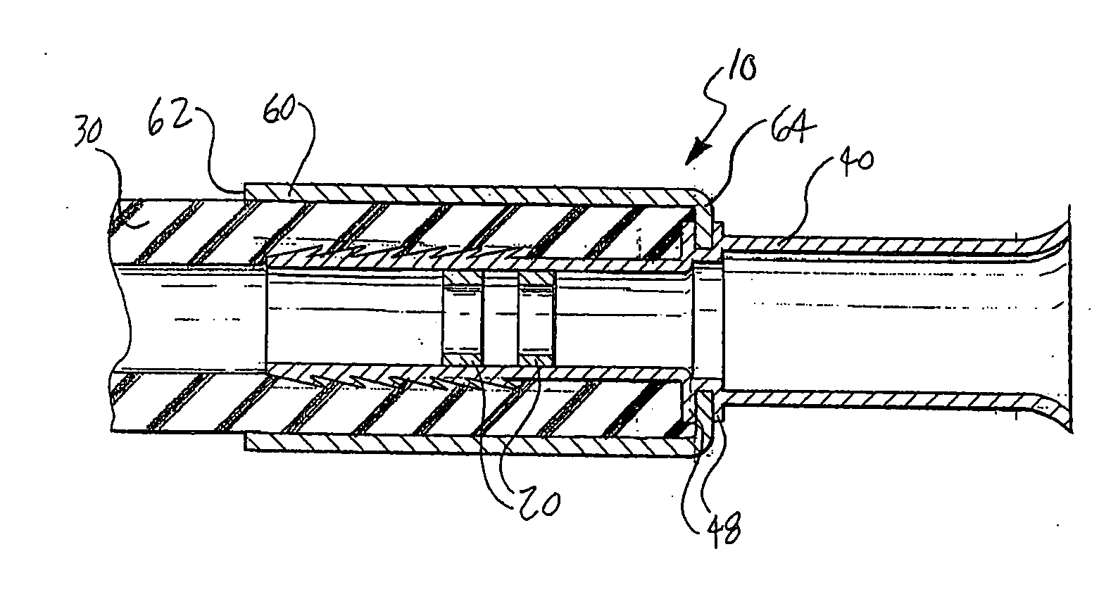
[0031] Referring to the Figures, particularly to FIGS. 1 and 2, there is shown a coupling 10 having at least one reinforcing ring 20 mounted therein according to the present invention. The reinforcing ring 20 is shown in perspective in FIG. 4. The coupling 10 connects a hose 30 to a cylindrical inner body or inner sleeve 40. The inner sleeve 40 may in turn be connected to other components of an air-conditioning system. The coupling 10 is generally used in automotive air-conditioning systems for transporting refrigerant fluid. However, the present invention may be used in any application for a connection requiring characteristics similar to those described herein.

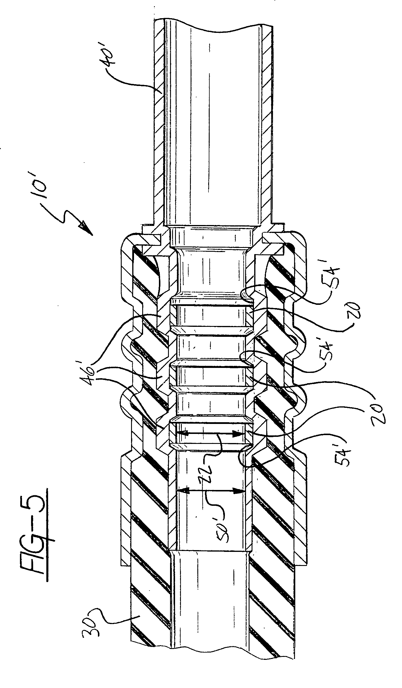
[0032] Referring now to FIG. 2, the inner sleeve 40 has a first end 42 over which the hose 30 is mounted and a second end 44 that is a termination point or acts to engage other components of the air-conditioning system. An outer diameter 45 of the inner sleeve 40 has outward projections or serrations 46 that engage and seal...


PUM

PropertyMeasurementUnit
inner diameteraaaaaaaaaa
outer diameteraaaaaaaaaa
pressureaaaaaaaaaa

Abstract

A hose coupling using at least one reinforcing ring to reinforce a hose coupling during a crimping process, the hose coupling having an inner sleeve, an outer sleeve coaxial with the inner sleeve, and a hose coaxially interposed therebetween. During the crimping process a crimping force is applied directly to the outer sleeve to form at least one depression that results in an area of peak crimp force on the inner sleeve, the depression helping to seal and lock the hose between the inner and outer sleeves. The reinforcing ring is positioned within the inner sleeve and concentric with the area of peak crimp force on the inner sleeve. Consequently, the reinforcing ring prevents the inner sleeve from deforming under the crimping force, thereby ensuring the integrity and long-term durability of the hose coupling. The reinforcing ring preferably has an inside diameter equal to or greater than an inside diameter of the inner sleeve and is disposed within at least one groove located within the inner sleeve to permit unrestricted fluid flow through the hose coupling.

Description

CROSS REFERENCE TO RELATED APPLICATION [0001] This application claims benefit to U.S. patent application Ser. No. 09 / 393,482 filed on Sep. 10, 1999.FEDERALL SPONSORED RESEARCH OR DEVELOPMENT [0002] Not applicable. REFERENCE TO SEQUENCE LISTING [0003] Not Applicable BACKGROUND OF THE INVENTION [0004] 1. Field of the Invention [0005] The present invention relates generally to conduit couplings. More particularly, the present invention relates to a compact reinforcement to be used in a crimped coupling for high-pressure hose connections such as in an automotive air-conditioning system. [0006] 2. Description of the Prior Art[0007] It is generally known in the art relating to flexible conduit couplings to utilize a coupling member having a collar or concentric circular sleeves. The collar, or outer sleeve, is crimped over a hose circumscribing an inner sleeve in order to engage the hose to the coupling member and create a sealed coupling. Generally, to resist the crimping forces, the inn...

Claims


Application Information

Patent Timeline
Patent Type & Authority Applications(United States)
IPC IPC(8): F16L33/22
CPCY10T29/49911F16L33/2076
Inventor CHISNELL, JERRY H.
Owner HUTCHINSON FTS INC
Why Eureka
Try Eureka