Chambers for a hearing instrument shell

a hearing instrument and chamber technology, applied in the field of chambers for hearing instruments, can solve the problems of catching on the inside of the shell, the end of the tube missing the receiver tube hole, etc., and achieve the effect of reducing the tendency of the walls to vibrate and improving the assembly process

Inactive Publication Date: 2007-09-27
SIEMENS HEARING INSTRUMENTS
View PDF2 Cites 2 Cited by
  • Summary
  • Abstract
  • Description
  • Claims
  • Application Information

AI Technical Summary

Benefits of technology

[0012] The design discussed here will improve the assembly process. An additional benefit achieved by the configurations discussed here is that walls of the shell are reinforced, reducing any tendency of the walls to vibrate.

Problems solved by technology

Occasionally, the end of the tube misses the receiver tube hole and catches on the inside of the shell.

Method used


Image

  • Chambers for a hearing instrument shell
  • Chambers for a hearing instrument shell
  • Chambers for a hearing instrument shell

Examples


Embodiment Construction

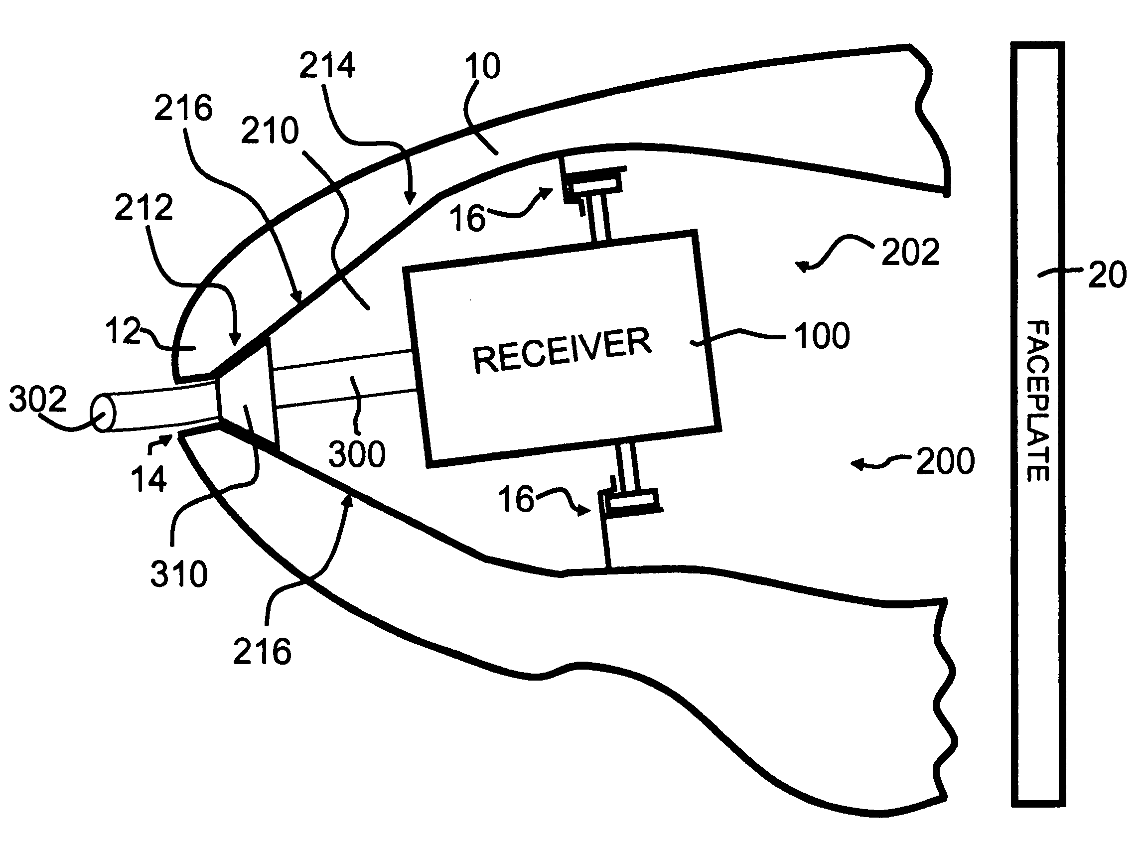
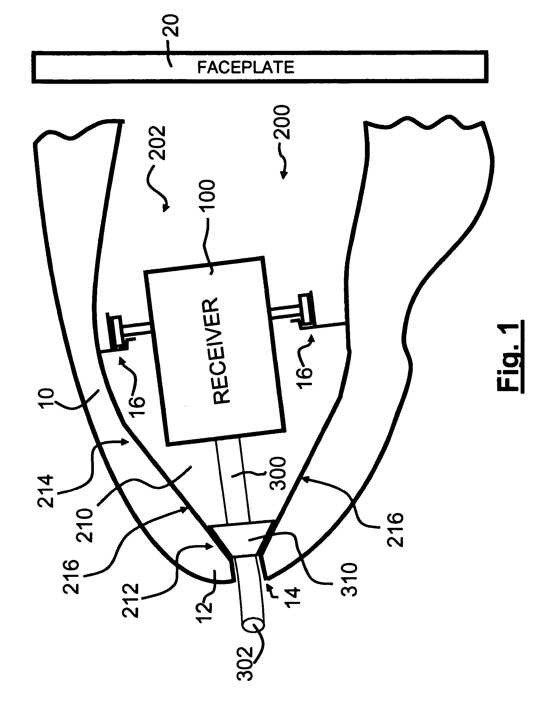
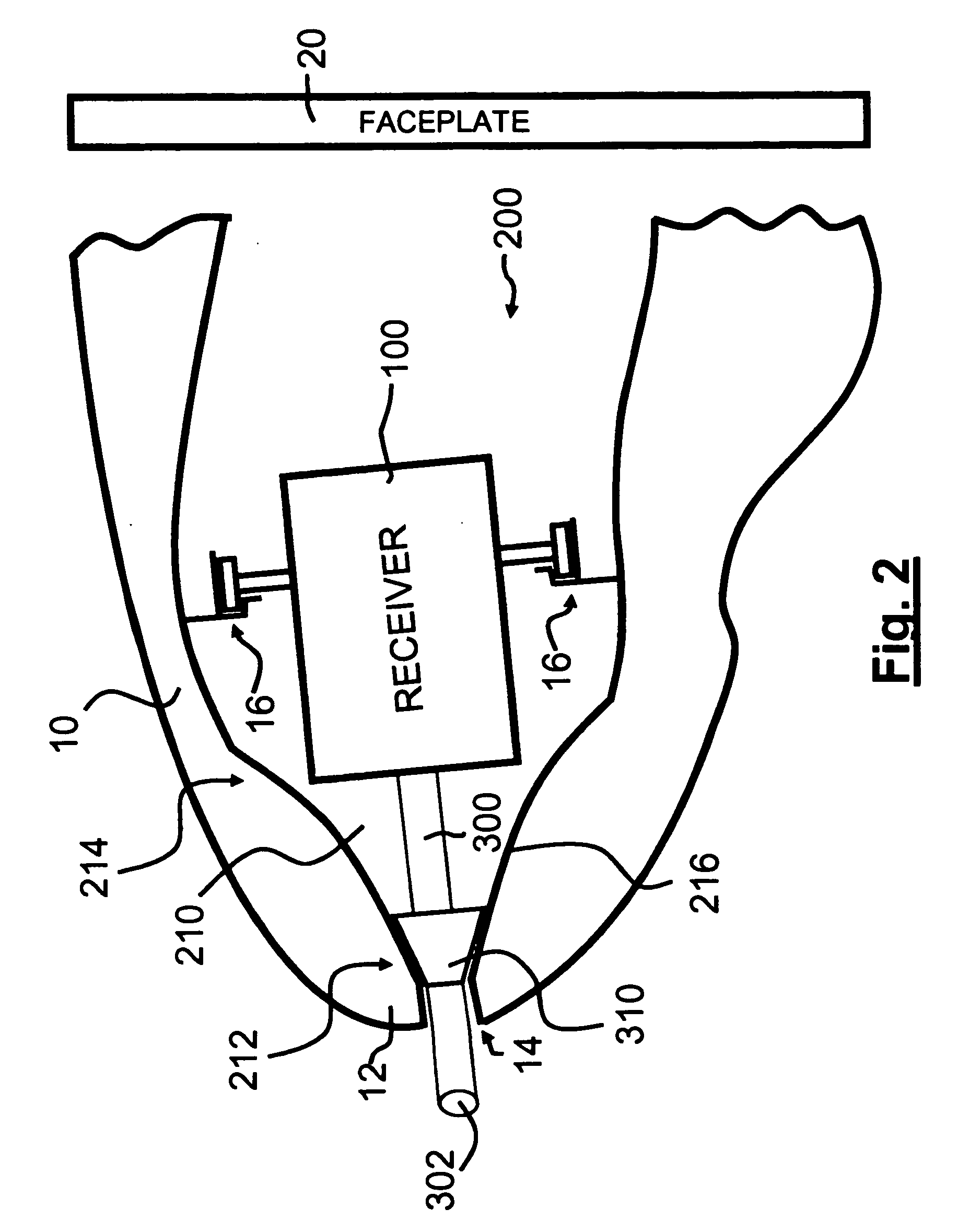
[0017]FIG. 1 is a partial cross-sectional view of a hearing instrument shell or housing 10, comprising a tip 12 to be inserted into the ear canal of the person wearing the hearing instrument. The other end of the shell 10, on the right side of FIG. 1, shown incomplete in this as well as the other figures, is where the faceplate 20 (shown schematically here) would be attached. The faceplate 20 is the portion of the hearing instrument that faces generally outwardly from the ear proper, and at least a portion of the faceplate 20 is typically visible in the outer ear. In addition to an opening to admit sound, the faceplate 20 may also contain a battery door and a volume control. The faceplate may be fabricated as an integral component of the housing or shell 10 or it may be a separate part attached to the housing or shell 10 during assembly.

[0018] A receiver assembly 100 is positioned in the interior 200 of the shell 10 and may be mounted there using anchors 16 such as those described ...


PUM


Abstract

A portion of a hearing instrument housing or shell comprises one or more chambers having planar, conical, or convex walls. During assembly, this shape helps guide the receiver tube towards tip of the shell and the receiver tube hole. Additionally, it will reinforce the walls of the shell, decreasing the tendency of the shell to vibrate when the receiver is generating sound.

Description

CROSS-REFERENCE TO RELATED APPLICATIONS [0001] This application is related to the following U.S. patent applications, incorporated herein by reference: [0002] Ser. No. 09 / 887,939 filed Jun. 22, 2001; [0003] Ser. No. 10 / 218,013 filed Aug. 13, 2002; [0004] Ser. No. 10 / 610,449 filed Jun. 30, 2003; and [0005] Ser. No. 10 / 945,704 filed Sep. 21, 2004.BACKGROUND AND SUMMARY OF THE INVENTION [0006] Hearing instruments, i.e., devices that assist the hearing impaired, designed for complete or partial insertion into the user's ear canal, have a shell or housing that holds various components. One such component is the receiver, the element that generates the sound heard by the instrument's user. The sound is carried from the receiver by a receiver tube affixed to a port on the receiver to an opening (the receiver tube hole) in the tip of the shell, the portion of the hearing instrument positioned in the ear canal towards the eardrum. [0007] During assembly, the receiver and its receiver tube ar...

Claims


Application Information

Patent Timeline
Patent Type & Authority Applications(United States)
IPC IPC(8): H04R25/00H04R25/02
CPCH04R25/652H04R25/608H04R25/609
Inventor SALTYKOV, OLEG
Owner SIEMENS HEARING INSTRUMENTS
Why Eureka
Try Eureka