Novel surface structures and methods thereof

a surface structure and technology of a new type of structure, applied in the direction of protective foundations, construction, foundation engineering, etc., can solve the problems of reducing the effect of excavation and site manipulation, limiting environmental impacts on surface and subsurface water flows, soil biological functions, etc., to preserve structural integrity, biological life, moisture conten

Inactive Publication Date: 2007-09-27
GAGLIANO RICHARD J
View PDF9 Cites 2 Cited by
  • Summary
  • Abstract
  • Description
  • Claims
  • Application Information

AI Technical Summary

Benefits of technology

[0009] An object of this invention is to provide an improved foundation that preserves the inherent structural integrity, moisture content, and biological life of its engaged soil.
[0012] An object of this invention is to provide an improved foundation that can withstand frost and expanding soil conditions without jeopardizing structural function.
[0014] An object of this invention is to provide an improved process for preparing a cementious structural foundation body through which piles are driven, but without the use of embedded sleeves or selectively re-enforcing elements.

Problems solved by technology

These technologies reduce the effects of excavation and site manipulation, thereby limiting environmental impacts to surface and subsurface water flows, and soil biological functions.

Method used


Image

  • Novel surface structures and methods thereof
  • Novel surface structures and methods thereof
  • Novel surface structures and methods thereof

Examples


first embodiment

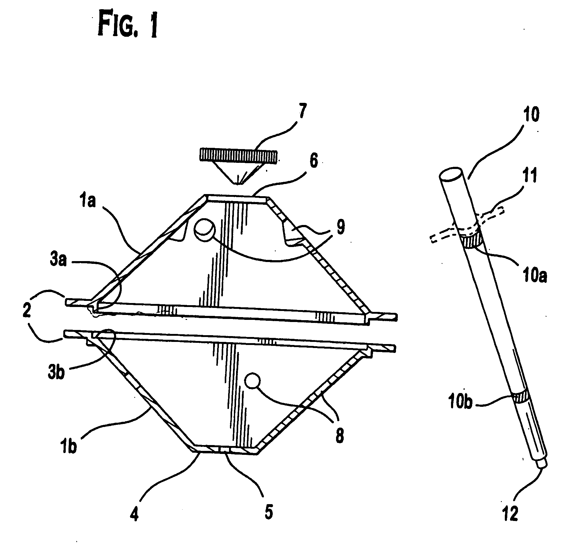
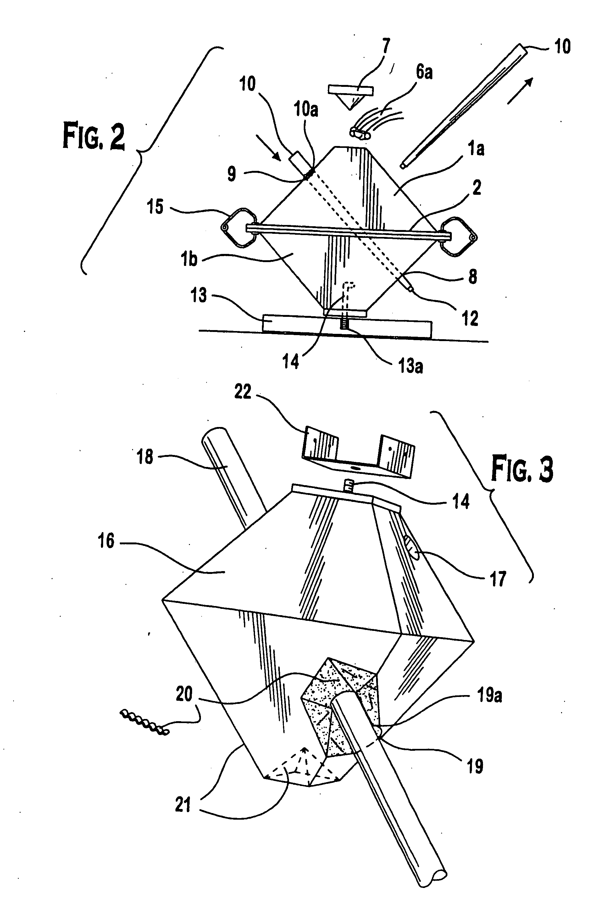
[0026] Referring now to FIG. 1, views of the primary components used in the inventive process to create the first embodiment are shown. There is a section view of a two part thermoplastic form 1a. and 1b, with side flanges 2 including a flange male and female interlock 3a and 3b. The form 1b. has a square shaped top 4, though this could be of any desired geometry, circular, rectangular, triangular, with a centered hole 5 for the placement of an embedded anchor bolt (see component 14, FIGS. 2 and 3). The form 1a. has an open end 6 for receiving a poured, curable cementious medium, and the subsequent placement of a pyramidal shaped plug 7. The use of this plug 7 will be more fully described in FIGS. 2 and 3, and in the example description. The main walls of the forms la. and 1b. are angled at approximately 45 degrees relative to the side flanges 2 and / or the top square plane 4. These sides contain round holes 8 in form 1b, and opposing, corresponding dimpled round holes 9 in form 1a. ...

second embodiment

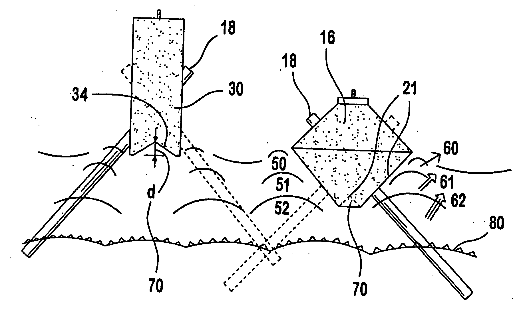
[0040]FIG. 4 is a variation on the first embodiment, creating a more rectilinear shaped structural body 30, which may be cast as a block to support point loads as in the first embodiment, but is more naturally employed as a continuous or longitudinal section of fixed width and utilizing a series of paired cast cavities along its length. In this application, rather than a top and bottom form, side forms 31a and 31b are employed. They are connected at the top and base by a restricting element 32 preventing the lateral outward movement of the forms under internal side pressures from the cementious pour. These restricting cleats are common in industry and do not represent an inventive step. The wedge block 33 is employed similar to the plug element 7 in FIG. 2. It is continuous along the full length of the forms, and will generate the necessary base shape 34 in the final cast body. The forms have round holes 8 in a section of the form shaped to be perpendicular to the axis of the dowel,...


PUM


Abstract

A novel foundation system, method of manufacture and method of implementation are disclosed, comprising a simplified cast structure / pile combination advantageously shaped for selective positioning in different soil conditions to become a supporting foundation. In at least one aspect, the shape comprises a cavity or shaped recess that is initially empty, and operable to accept soil displaced by soil heave. The cavity preferably is configured to have a depth estimated to be equal to or greater that an estimated vertical heave displacement of a given site soil, in order to minimize soil heave displacement of the cast structure / pile combination. In at least one other aspect, the shape comprises a portion configured to cleave soil if the soil heaves.

Description

CROSS REFERENCE TO RELATED APPLICATIONS [0001] This application is a divisional application of U.S. patent application Ser. No. 11 / 149,047, filed Jun. 8, 2005, which is a continuation-in-part of U.S. patent application Ser. No. 10 / 633,155 (now U.S. Pat. No. 6,910,832), filed Jul. 31, 2003. The entire contents of those applications are incorporated herein by reference.FIELD OF THE INVENTION [0002] The present invention generally relates to systems for the support of surface structures. More specifically the present invention relates to improvements to hybrid foundation systems comprised of piles and engaging cementious components, and to the methods and processes for preparing them. BACKGROUND OF THE INVENTION [0003] The construction of surface structures based on the rising concern for sustainable use of materials and developable lands leads in many cases to the use of minimal ground impact foundation technologies. These technologies reduce the effects of excavation and site manipul...

Claims


Application Information

Patent Timeline
Patent Type & Authority Applications(United States)
IPC IPC(8): E02D31/00E02D27/14
CPCE02D27/14E02D27/02
Inventor GAGLIANO, RICHARD J.
Owner GAGLIANO RICHARD J
Why Eureka
Try Eureka