Novel surface structures and methods thereof
a surface structure and technology of a new type of structure, applied in the direction of walls, foundation engineering, forms/shuttering/falseworks, etc., can solve the problems of limiting environmental impacts on surface and subsurface water flows, soil biological functions, excavation and site manipulation effects, etc., to preserve structural integrity, biological life, moisture content
- Summary
- Abstract
- Description
- Claims
- Application Information
AI Technical Summary
Benefits of technology
Problems solved by technology
Method used
Image
Examples
first embodiment
[0025] First Embodiment
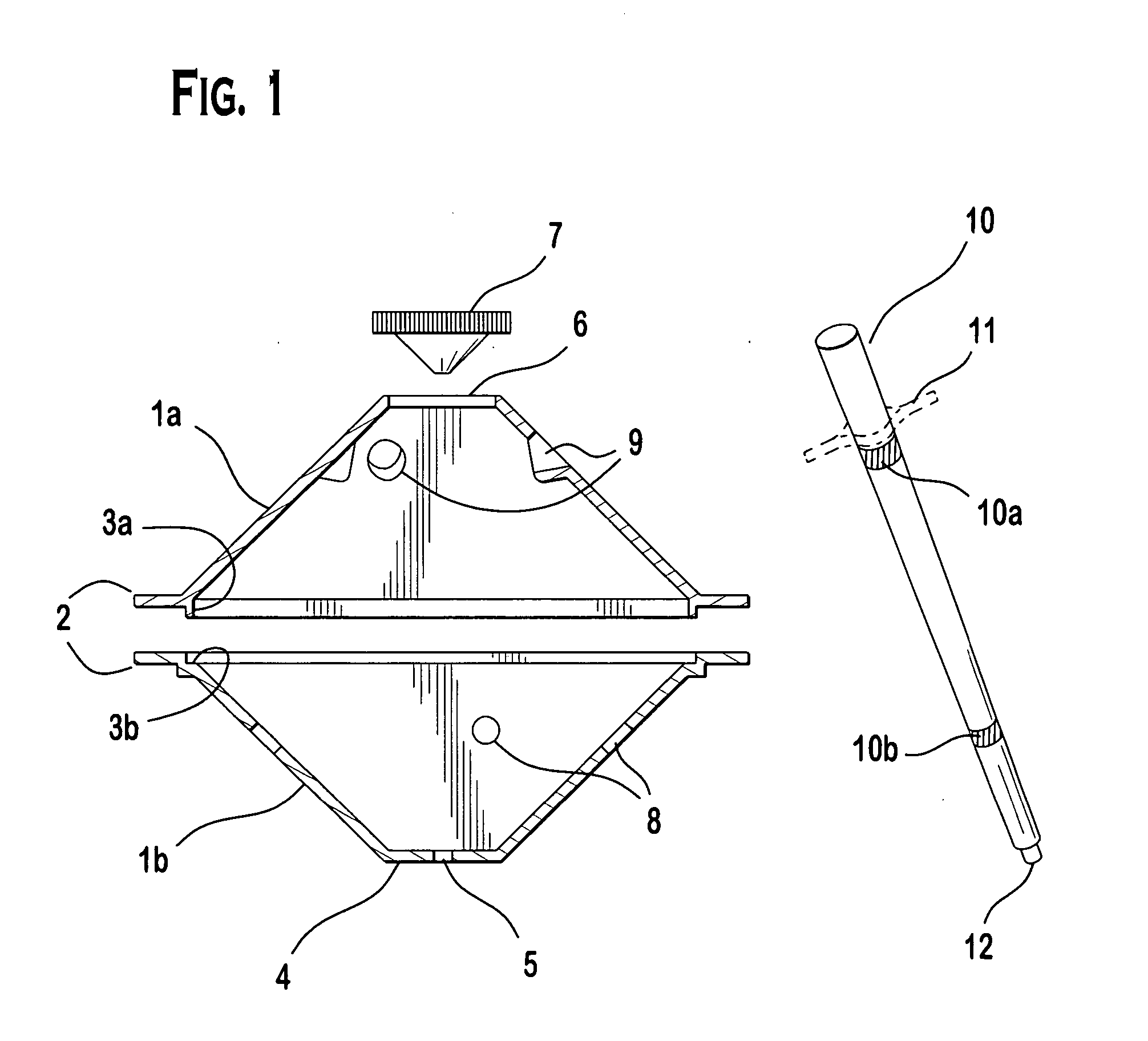
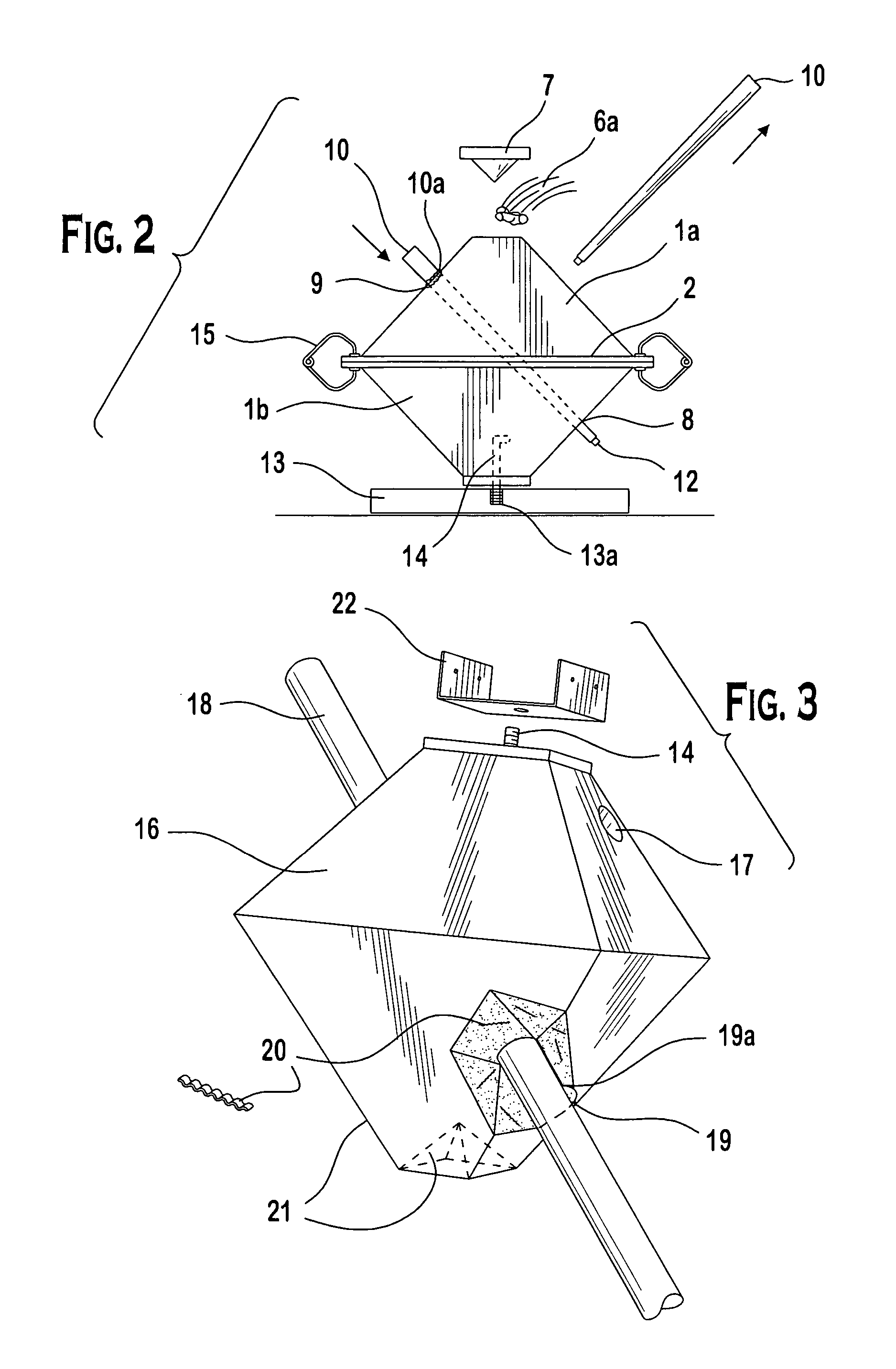
[0026] Referring now to FIG. 1, views of the primary components used in the inventive process to create the first embodiment are shown. There is a section view of a two part thermoplastic form 1a. and 1b., with side flanges 2 including a flange male and female interlock 3a and 3b. The form 1b. has a square shaped top 4, though this could be of any desired geometry, circular, rectangular, triangular, with a centered hole 5 for the placement of an embedded anchor bolt (see component 14, FIGS. 2 and 3). The form 1a. has an open end 6 for receiving a poured, curable cementious medium, and the subsequent placement of a pyramidal shaped plug 7. The use of this plug 7 will be more fully described in FIGS. 2 and 3, and in the example description. The main walls of the forms 1a. and 1b. are angled at approximately 45 degrees relative to the side flanges 2 and / or the top square plane 4. These sides contain round holes 8 in form 1b., and opposing, corresponding dimpled r...
second embodiment
[0040] Second Embodiment
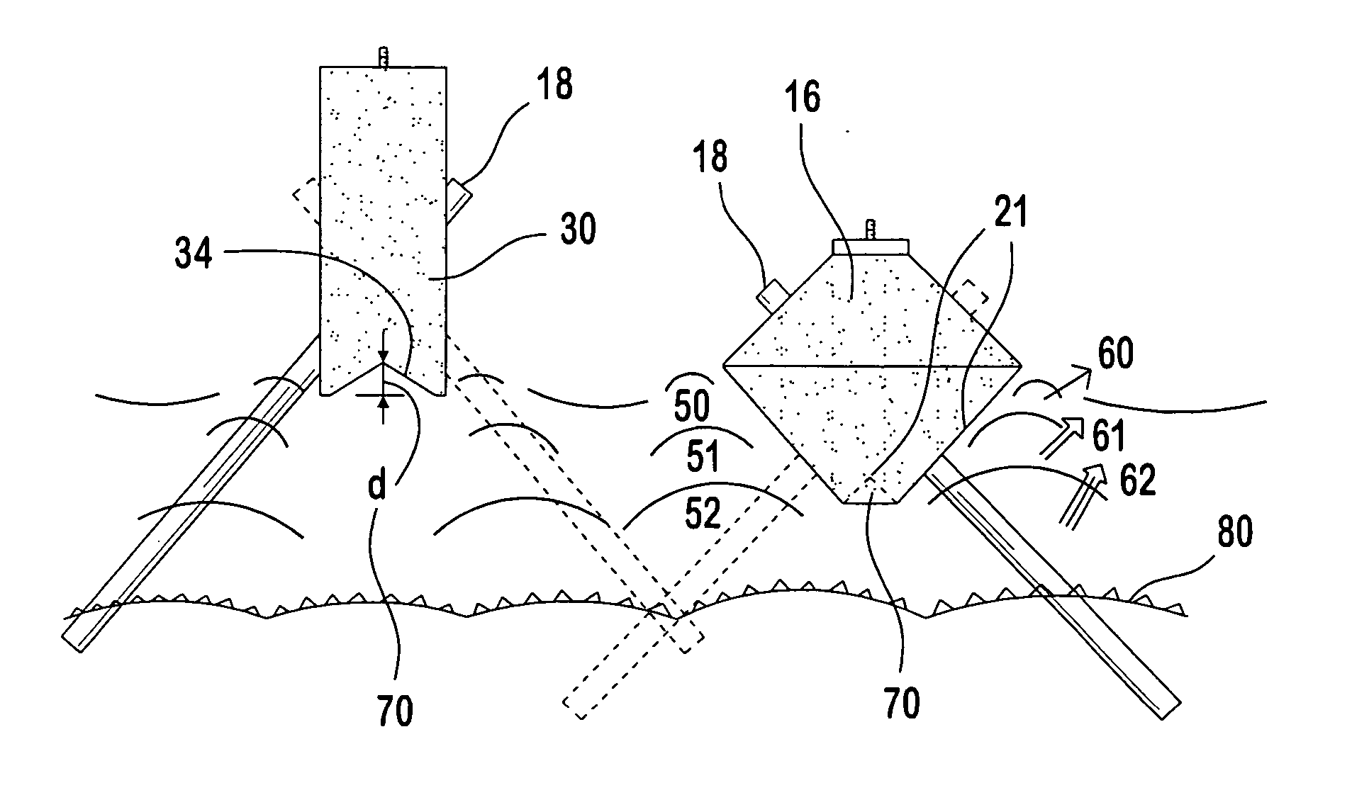
[0041]FIG. 4 is a variation on the first embodiment, creating a more rectilinear shaped structural body 30, which may be cast as a block to support point loads as in the first embodiment, but is more naturally employed as a continuous or longitudinal section of fixed width and utilizing a series of paired cast cavities along its length. In this application, rather than a top and bottom form, side forms 30a. and 30b. are employed. They are connected at the top and base by a restricting element 32 preventing the lateral outward movement of the forms under internal side pressures from the cementious pour. These restricting cleats are common in industry and do not represent an inventive step. The wedge block 33 is employed similar to the plug element in FIG. 2. It is continuous along the full length of the forms, and will generate the necessary base shape 34 in the final cast body. The forms have round holes 8 in a section of the form shaped to be perpendicular t...
PUM
| Property | Measurement | Unit |
|---|---|---|
| set time | aaaaa | aaaaa |
| set time | aaaaa | aaaaa |
| set time | aaaaa | aaaaa |
Abstract
Description
Claims
Application Information
 - R&D
- Intellectual Property
- Life Sciences
- Materials
- Tech Scout
- Unparalleled Data Quality
- Higher Quality Content
- 60% Fewer Hallucinations
Browse by: Latest US Patents, China's latest patents, Technical Efficacy Thesaurus, Application Domain, Technology Topic, Popular Technical Reports.
© 2025 PatSnap. All rights reserved.Legal|Privacy policy|Modern Slavery Act Transparency Statement|Sitemap|About US| Contact US: help@patsnap.com


