
Variable displacement sliding vane pump

a sliding vane pump and variable displacement technology, which is applied in the direction of machines/engines, rotary/oscillating piston pump components, liquid fuel engines, etc., can solve the problems of reducing the amount of fluid drawn into the pump, the amount of fluid output of the pump, and the oil pressure as well

Inactive Publication Date: 2007-09-27
STACKPOLE POWERTRAIN INT ULC
View PDF17 Cites 51 Cited by
  • Summary
  • Abstract
  • Description
  • Claims
  • Application Information

AI Technical Summary

Problems solved by technology

This reduces the amount of fluid drawn into the pump from the fluid reservoir and likewise, the amount of fluid output by the pump and thereby reduces the oil pressure as well.

Method used


Image

  • Variable displacement sliding vane pump
  • Variable displacement sliding vane pump
  • Variable displacement sliding vane pump

Examples


Embodiment Construction

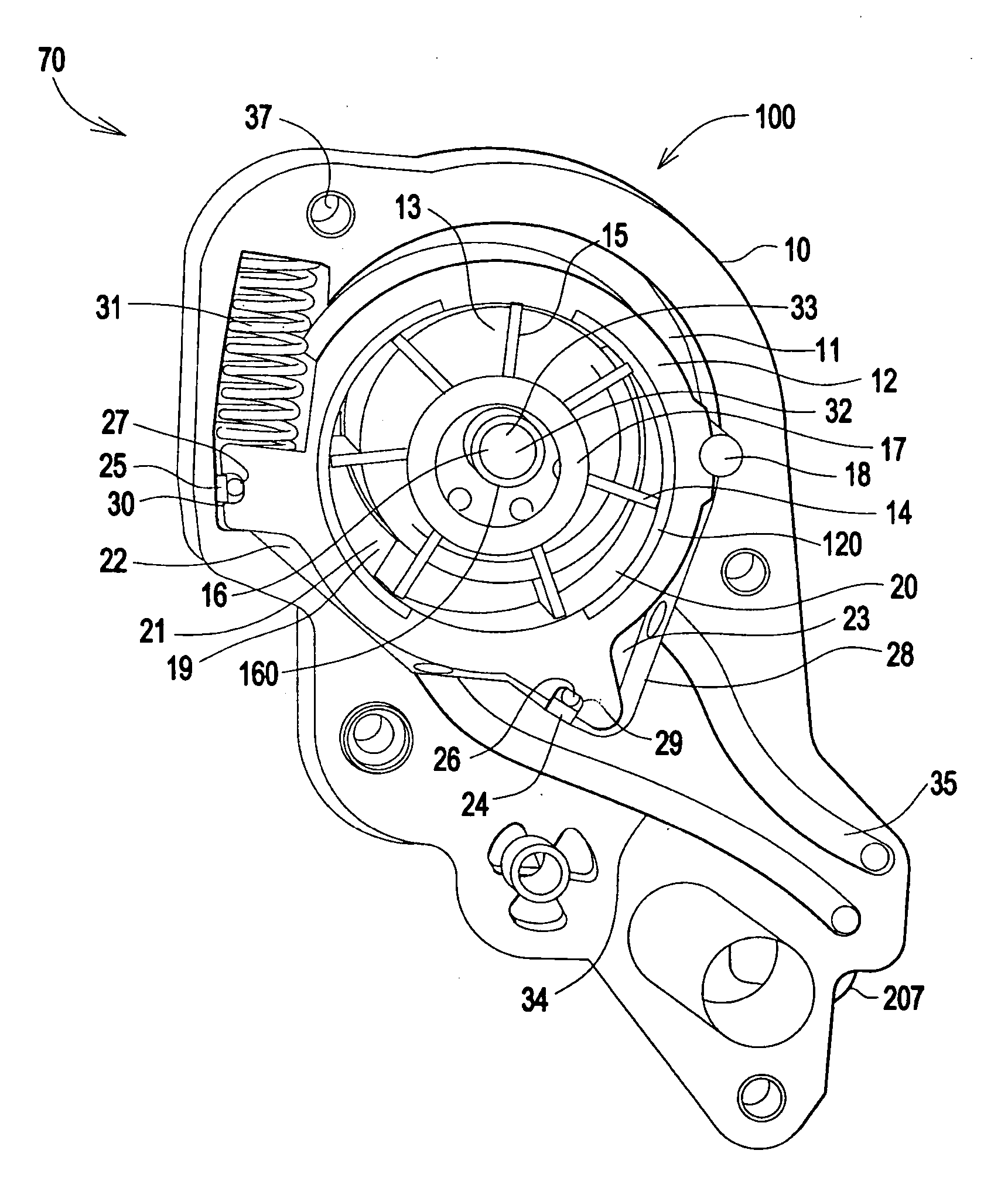
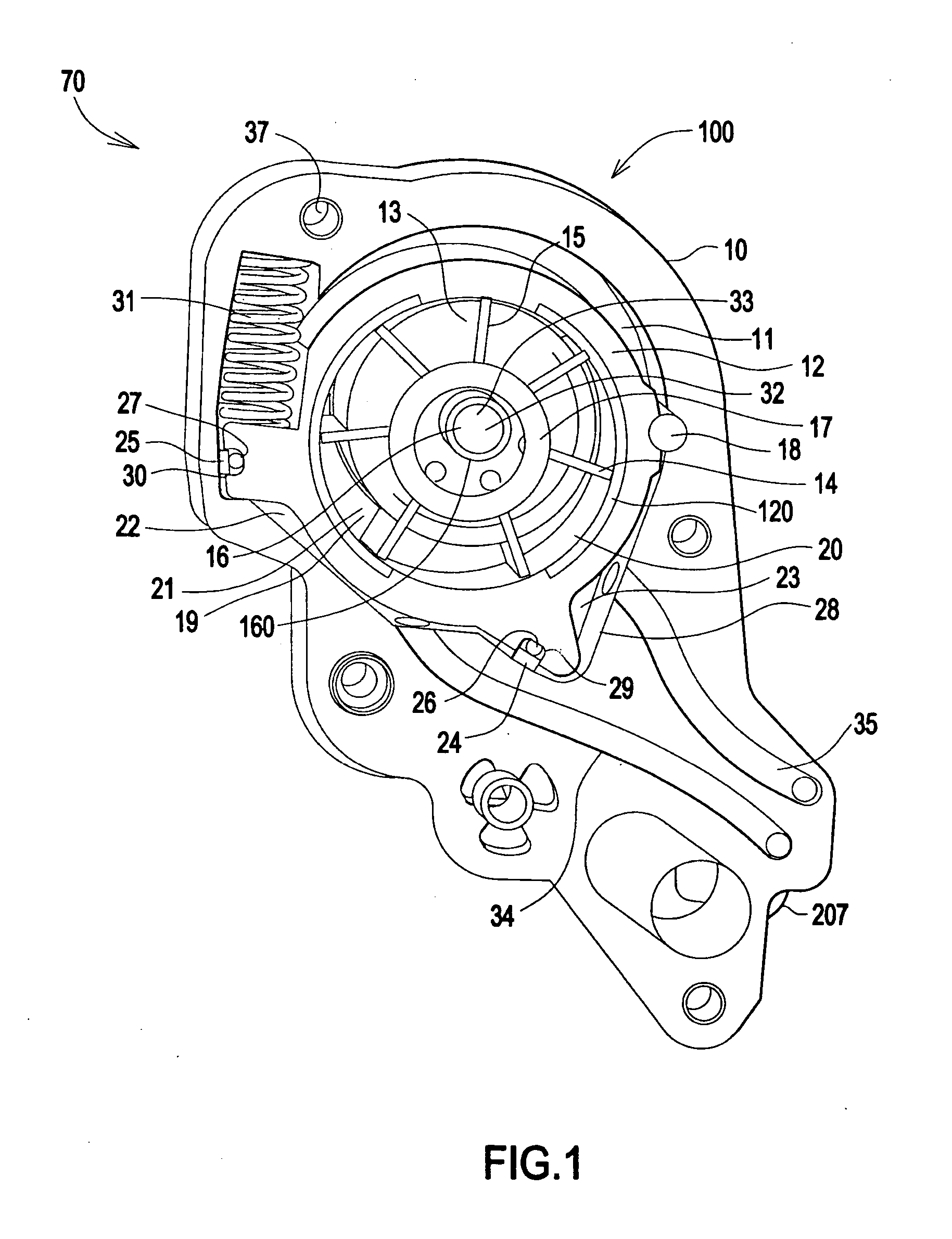
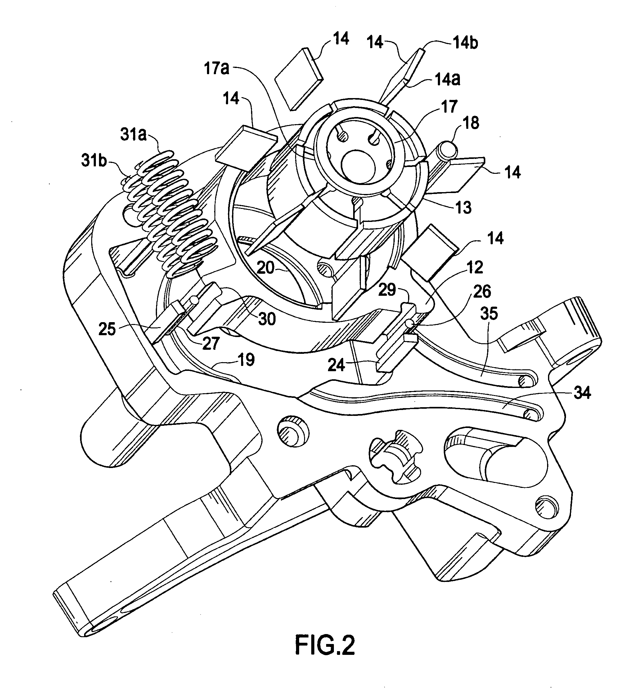
[0020]FIG. 1 is a front view of the pump with outer cover removed. The inventive pump 100 comprises body 10. Body 10 defines a cavity 11 within which is disposed slide 12 and rotor 13. A plurality of sliding vanes 14 are radially disposed about rotor 13. Each vane 14 extends radially from a slot 15 in rotor 13. Each vane 14 is moveable within each slot 15.

[0021] Pump shaft 16 is rotatably mounted in body 10. A splined end 160 of pump shaft 16 engages rotor 13. As rotor 13 rotates vanes 14 are urged outwardly by a pair of vane control rings 17 and centripetal force into a sliding engagement with inner surface 120 of slide 12.

[0022] Slide 12 is pivotally engaged with the body at a pivot member 18. Slide 12 pivots at pivot member 18 within cavity 11 thereby describing an arc which defines the operating range of motion of slide 12.

[0023] The position of each vane 14 is a function of the position of slide 12 with respect to ring 17. Ring 17 occupies a space determined by the ends of v...


PUM


Abstract

A variable displacement sliding vane pump comprising a pump body, inlet and outlet ports formed in said pump body, a drive shaft rotatably mounted in said pump body, a rotor driven by said drive shaft and co-axially aligned therewith, a plurality of radially extending vanes slidably disposed in said rotor, a pivot disposed in said pump body, a slide pivotally disposed on said pivot in said pump body and having a central axis eccentric to the axis of said rotor, a plurality of fluid chambers defined by said rotor, said vanes, and said slide that are successively connected to said inlet and outlet ports, a spring acting on said slide to urge said slide in one direction, a first chamber and a second chamber, each suitable for receiving a fluid pressure and each disposed between said pump body and an outer surface of said slide, the first chamber in fluid communication with a pump outlet discharge pressure, and a valve operable to selectively pressurize and depressurize the second chamber.

Description

FIELD OF THE INVENTION [0001] The invention relates to a variable displacement sliding vane pump having a slide whose position is controlled by a differential pressure between a constant pressure source and a variable pressure source, the differential pressure equilibrating a spring force applied to the slide to establish a desired flow rate and pressure. BACKGROUND OF THE INVENTION [0002] A lubrication system for an engine pressurizes and distributes lubrication fluid to the engine lubrication circuits. It employs a rotor and a slide with multiple vanes and cavities which can vary the volume of fluid delivered to the oil circuits. [0003] The slide is eccentrically offset from the rotor to create fluid chambers defined by the vanes, rotor, and inner surface of the slide. A compression spring positions the slide to create large fluid chambers as the default. When the engine requires less volume of fluid or less oil pressure by the pump, a pressure regulator directs fluid from the pum...

Claims


Application Information

Patent Timeline
IPC IPC(8): F01C20/18F01C19/00F01C19/02
CPCF04C14/226F04C2/344F04C14/22
Inventor ARNOLD, MANFREDMOOY, ROBERT H.MORTON, PAUL M.
Owner STACKPOLE POWERTRAIN INT ULC
Learn More