Apparatus, system, and method for diverting fluid

a technology of diverting fluid and apparatus, applied in the direction of liquid fuel feeders, machines/engines, liquid transferring devices, etc., can solve the problems of reducing the flow rate and fluid pressure below the specified flow rate and pressure range, mechanical devices may require a costly separate auxiliary fluid supply system including additional pumps, and low-pressure fluid may not be easily accessible. , to achieve the effect of reducing the cost of adding

Active Publication Date: 2007-10-04
CUMMINS FILTRATION IP INC
View PDF8 Cites 10 Cited by
  • Summary
  • Abstract
  • Description
  • Claims
  • Application Information

AI Technical Summary

Benefits of technology

[0014] The primary coupler connects to the port. In addition, the primary coupler communicates low-pressure fluid to the pump component. The diverter fluid passage diverts the low-pressure fluid from the pri

Problems solved by technology

Unfortunately, the diversion of fuel from a high-pressure fluid pump may reduce the flow rate and fluid pressure below the specified flow rate and pressure ranges.
As a result, the mechanical device may require a costly separate auxiliary fluid supply system including additional pumps, filters, regulators, and contro

Method used


Image

  • Apparatus, system, and method for diverting fluid
  • Apparatus, system, and method for diverting fluid
  • Apparatus, system, and method for diverting fluid

Examples


Embodiment Construction

[0031] Reference throughout this specification to “one embodiment,”“an embodiment,” or similar language means that a particular feature, structure, or characteristic described in connection with the embodiment is included in at least one embodiment of the present invention. Thus, appearances of the phrases “in one embodiment,”“in an embodiment,” and similar language throughout this specification may, but do not necessarily, all refer to the same embodiment.

[0032] Furthermore, the described features, structures, or characteristics of the invention may be combined in any suitable manner in one or more embodiments. In the following description, numerous specific details are provided, such as examples of pumps, pump components, loads, to provide a thorough understanding of embodiments of the invention. One skilled in the relevant art will recognize, however, that the invention can be practiced without one or more of the specific details, or with other methods, components, materials, an...


PUM


Abstract

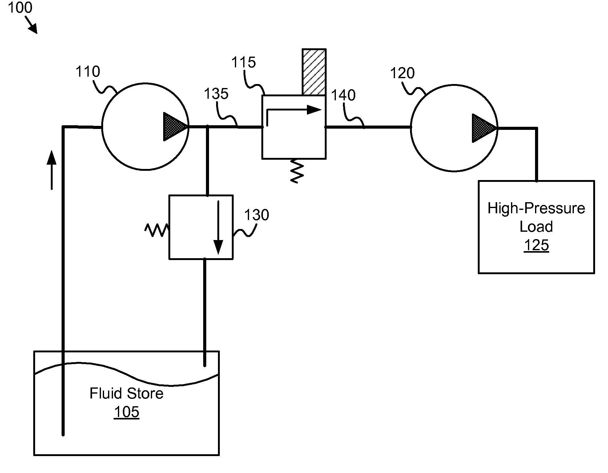
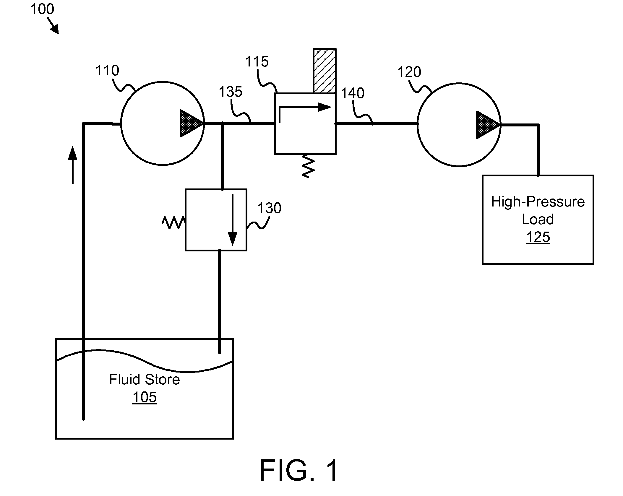
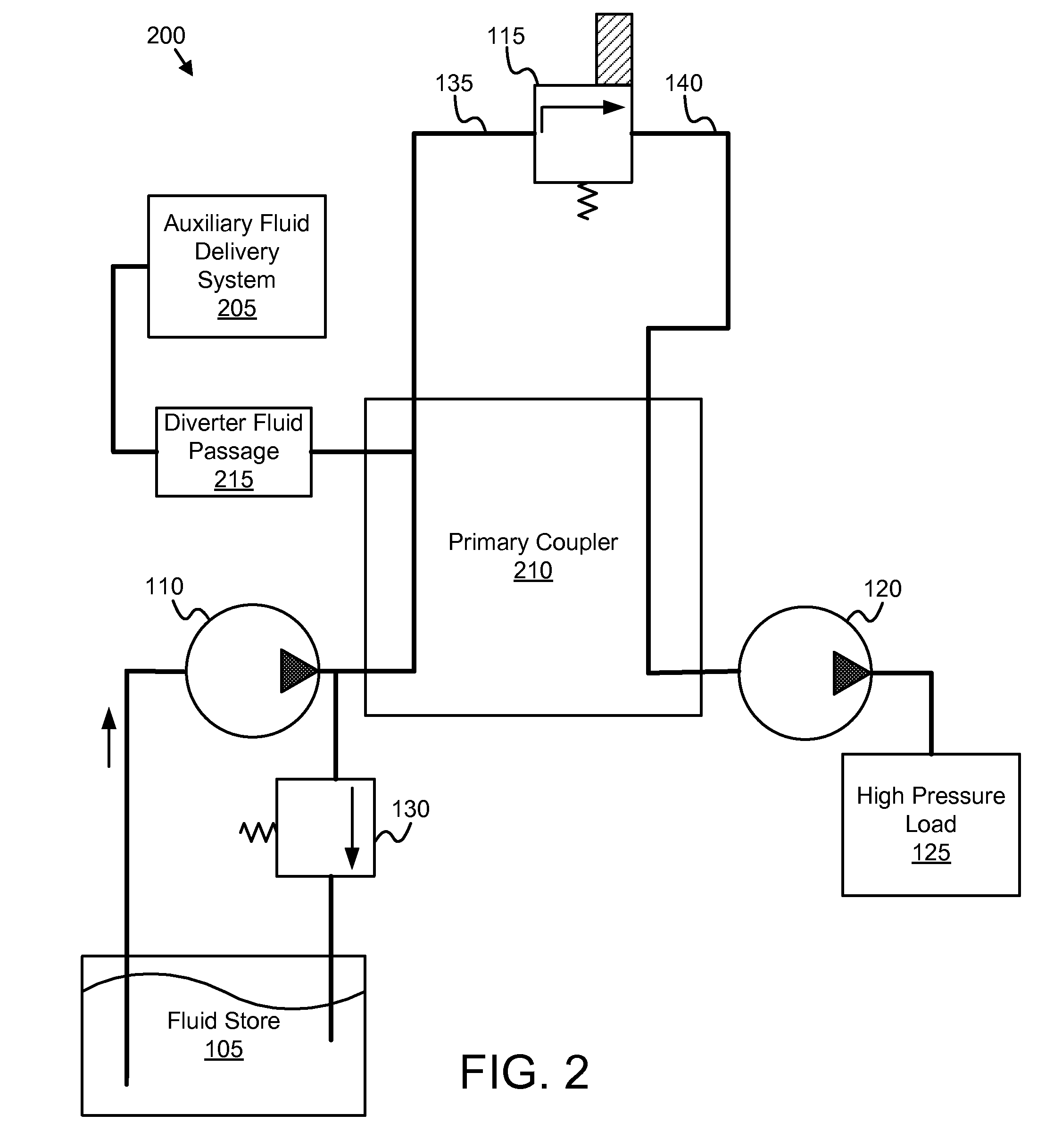
A pump component is removed from a port of a suction-side fluid cavity of a high-pressure fluid pump. The pump component performs a pump function for the high-pressure fluid pump. A primary coupler connects to the port. The pump component connects to the primary coupler. A diverter fluid passage diverts a low-pressure fluid from the primary coupler to an auxiliary fluid delivery system. The primary coupler communicates the low-pressure fluid through the pump component and primary coupler to the port.

Description

CROSS-REFERENCES TO RELATED APPLICATIONS [0001] This application is a continuation-in-part of and claims priority to U.S. patent application Ser. No. 11 / 156,682 entitled “APPARATUS, SYSTEM, AND METHOD FOR INTERMITTENTLY DELIVERING FLUID” and filed on Jun. 20, 2005 for John T. Carroll III and Laszlo D. Tikk, which is incorporated herein by reference.BACKGROUND OF THE INVENTION [0002] 1. Field of the Invention [0003] This invention relates to diverting fluid and more particularly relates to diverting fluid from a high-pressure pump. [0004] 2. Description of the Related Art [0005] A mechanical device such as an internal combustion engine often includes a high-pressure fluid pump. For example, a diesel engine may include a high-pressure fuel pump to deliver fuel from a storage tank to a fuel injection system. The mechanical device typically requires the high-pressure fluid pump to deliver the fluid within specified flow rate and pressure ranges. Devices receiving the fluid often only fu...

Claims


Application Information

Patent Timeline
IPC IPC(8): F02M37/04B67D7/70
CPCF01N3/2066F01N3/36F01N2270/02Y02T10/24F01N2610/14F01N2610/1446F02M37/0047F01N2610/03Y02T10/12Y10T137/86131Y10T137/87273
Inventor CARROLL, JOHN T. IIITIKK, LASZLO D.
Owner CUMMINS FILTRATION IP INC
Why Eureka
Try Eureka