
Method of retarding injection timing of mechanical unit injectors using a modified pump barrel

a technology of mechanical unit injector and pump barrel, which is applied in the direction of positive displacement liquid engine, pump, machine/engine, etc., can solve the problems of nitrous oxide and particulate emissions, human error potential, and plaguing problems, so as to reduce the amount of nitrogen oxides emitted

Inactive Publication Date: 2007-10-04
HAYNES CORP
View PDF13 Cites 2 Cited by
  • Summary
  • Abstract
  • Description
  • Claims
  • Application Information

AI Technical Summary

Benefits of technology

[0009] The primary object of the present invention is to provide a method of retarding injection timing of mechanical unit injectors which reduces the amount of nitrogen oxides emitted from a diesel engine.
[0010] Another object of the present invention is to provide a method of retarding injection timing of mechanical unit injectors that does not require specifying a new timing distance.
[0011] An even further object of the present invention is to provide a method of retarding injection timing of mechanical unit injectors that does not require the providing of a new setting gauge and / or new engine marking.
[0012] Another object of the present invention is to provide a method of retarding injection timing of mechanical unit injectors that could be used on all diesel engines.

Problems solved by technology

However, it is the nitrous oxides and particulate emissions that remain one of the plaguing problems for diesel engines.
This variation creates a potential for human error wherein a mechanic must use multiple gages to set multiple engines.

Method used


Image

  • Method of retarding injection timing of mechanical unit injectors using a modified pump barrel
  • Method of retarding injection timing of mechanical unit injectors using a modified pump barrel
  • Method of retarding injection timing of mechanical unit injectors using a modified pump barrel

Examples


Embodiment Construction

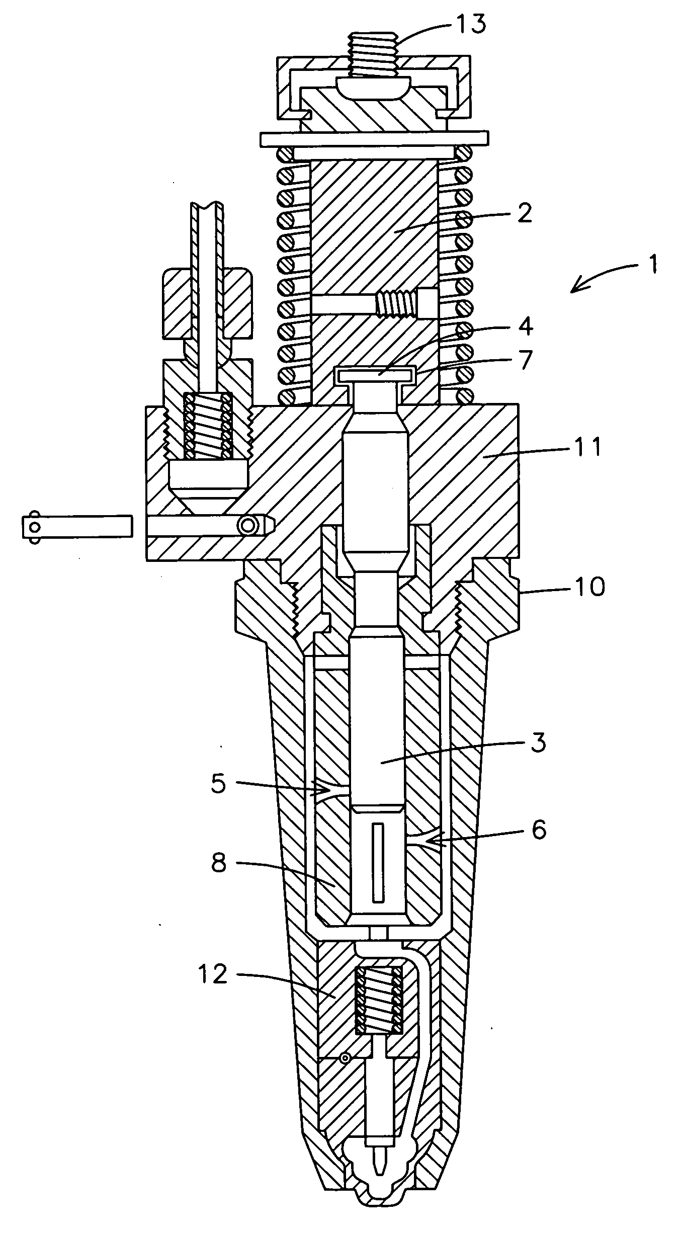
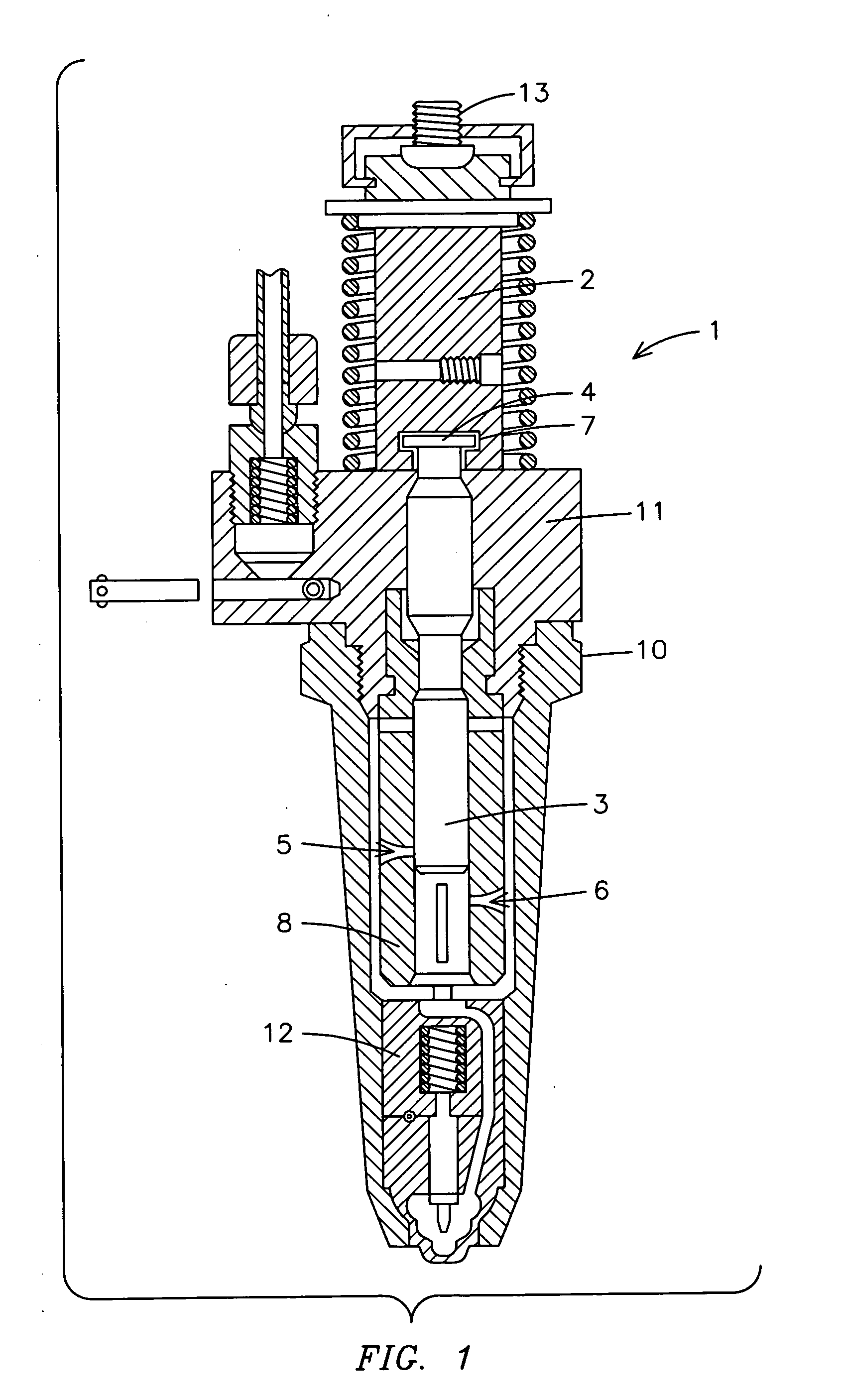
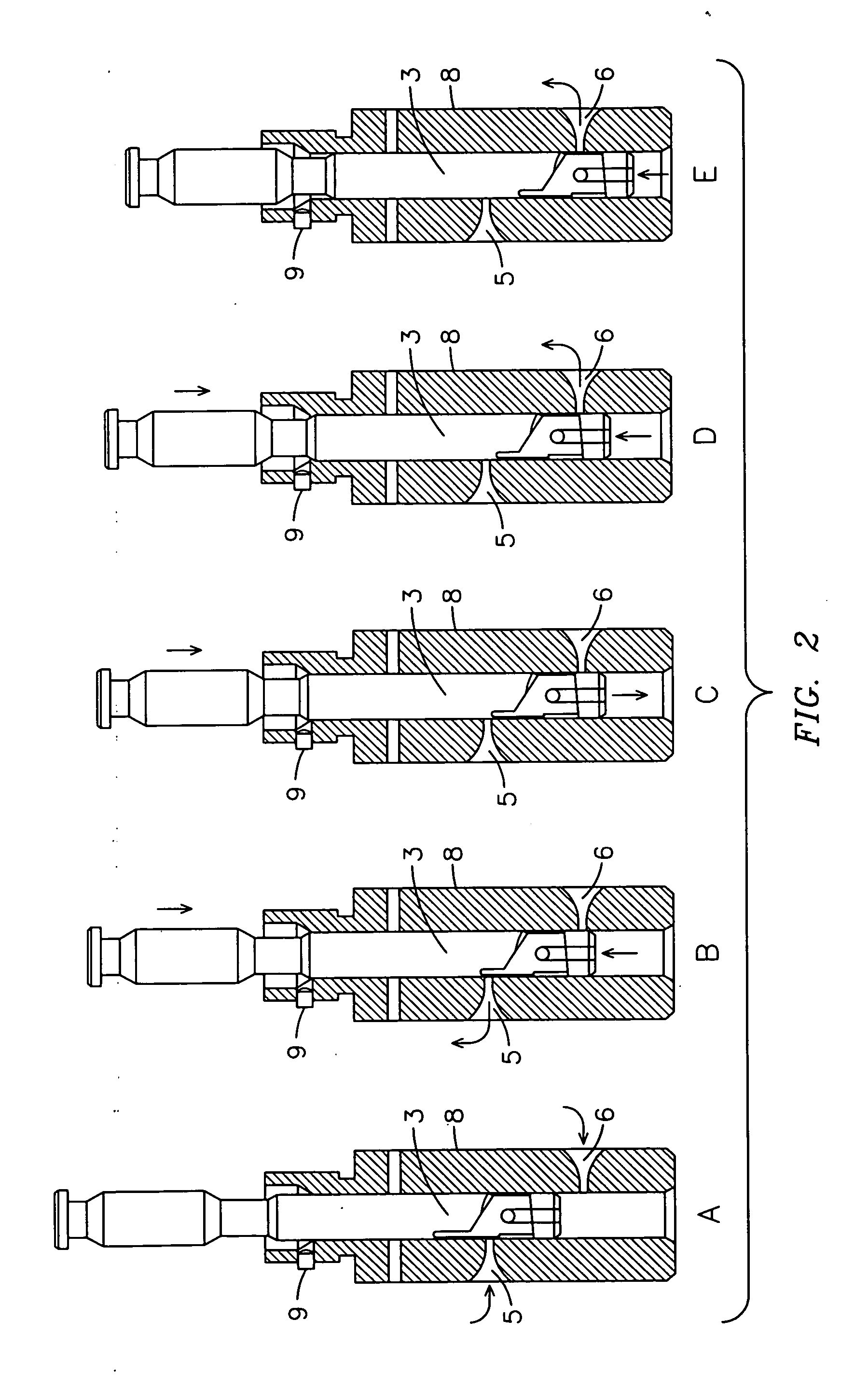
[0022] For purposes of describing the preferred embodiment, the terminology used in reference to the numbered components in the drawings is as follows:

[0023] 1. fuel injector, generally

[0024] 2. pump follower

[0025] 3. pump plunger

[0026] 4. plunger head

[0027] 5. top port

[0028] 6. bottom port

[0029] 7. t-slot

[0030] 8. pump barrel

[0031] 9. locating pin

[0032] 10. valve nut

[0033] 11. body

[0034] 12. cylinder

[0035] 13. adjusting screw

[0036] With reference to FIG. 1, a cut-away side view of a fuel injector of the present invention is shown. The fuel injector 1 includes a body 11 of a conventional unit injector. A valve nut 10 holds the pump barrel 8 of the present invention to the body 11. A pump plunger 3 having a plunger head 4 is slidably received within the pump barrel 8. A pump follower 2 having a t-slot 7 receives a plunger head 4 of the pump plunger 3. Thus, the pump plunger 3 and pump follower 2 are in end-to-end arrangement and move as one unit when in use. The pump ba...


PUM


Abstract

A modified barrel device (1) and method of retarding injection timing of EMD-type unit injectors by a desired amount of crank degrees includes the steps of providing a modified pump barrel (8) whose port locations differ, in their spacing from the top shoulder of the associated barrel, that corresponds to the spacing from the top face of the associated follower, from the spacing of the barrel port sealing location of the pump barrel of the original injector from the top shoulder of the associated barrel, that corresponds to the top face of the associated follower (2), such difference in spacing being by an amount equal to the amount of retardation, in linear units, that corresponds to the desired amount of retardation in crank degrees, and assembling the modified pump barrel (8) into an injector assembly.

Description

BACKGROUND OF THE INVENTION [0001] This invention relates to fuel injectors, more particularly, a modified pump barrel for use in retarding injection timing of EMD-type unit injectors in diesel engines. [0002] EMD-type unit injectors are injectors that feature mechanical unit injectors (as opposed to electronic control) and are widely used in the diesel engine industry, including the locomotive industry. However, with the increase of concern of harmful emissions from diesel engines and overall energy conservation, modifications to EMD-type unit injectors have become necessary so as to be more environmental friendly. [0003] Although the prevalence of photochemical smog in metropolitan areas spurred the first public interest in reducing noxious emissions from exhaust emissions, reducing output of all types of harmful emissions, including carbon monoxide (CO), hydrocarbons (HC) and nitrous oxides (NOx) has become one of the goals of the diesel engine industry. Through the years, the di...

Claims


Application Information

Patent Timeline
IPC IPC(8): F02M47/02F04B7/04
CPCF02M57/023F02M59/48F02M59/26
Inventor LEE, SCHULTZ GREGORYSCHLAIRET, ED A.HARRISON, EDWARD H.
Owner HAYNES CORP
Learn More