Method for Squeezing Foundry Sand, a Match Plate, and an Upper and a Lower Flask

a technology of foundry sand and squeezing machine, which is applied in the direction of manufacturing tools, moulding machines,foundry moulding apparatus, etc., can solve the problems of high hardness and strength near the inner surface of the match plate, of the upper and lower molds made by using the apparatus explained above, and the difficulty in achieving the effect of high hardness

Active Publication Date: 2007-10-04
SINTOKOGIO LTD
View PDF5 Cites 2 Cited by
  • Summary
  • Abstract
  • Description
  • Claims
  • Application Information

AI Technical Summary

Benefits of technology

[0012] a step to squeeze the foundry sand of the molding spaces by causing the upper and the lower squeeze plate to further approach each other.
[0016] a second squeezing step to squeeze the foundry sand in the upper and the lower molding space by causing the pattern portions of the match plate to move to each of the upper and the lower squeeze plate.
[0027] Thus, since it becomes possible to further squeeze the foundry sand near the inner surface that corresponds to the match plate, of the upper and the lower flask, by causing the pattern portions of the match plate to move to each of the upper and the lower squeeze plate, it is possible to produce an upper and a lower mold having desirable hardness and strength near the inner surface of the upper and the lower flask. Namely, this invention has practical and excellent effects.

Problems solved by technology

However, the hardness and the strength near the inner surface that corresponds to the match plate, of the upper and the lower mold that are made by using the apparatus explained above, are not high enough.

Method used


Image

  • Method for Squeezing Foundry Sand, a Match Plate, and an Upper and a Lower Flask
  • Method for Squeezing Foundry Sand, a Match Plate, and an Upper and a Lower Flask
  • Method for Squeezing Foundry Sand, a Match Plate, and an Upper and a Lower Flask

Examples


embodiment 1

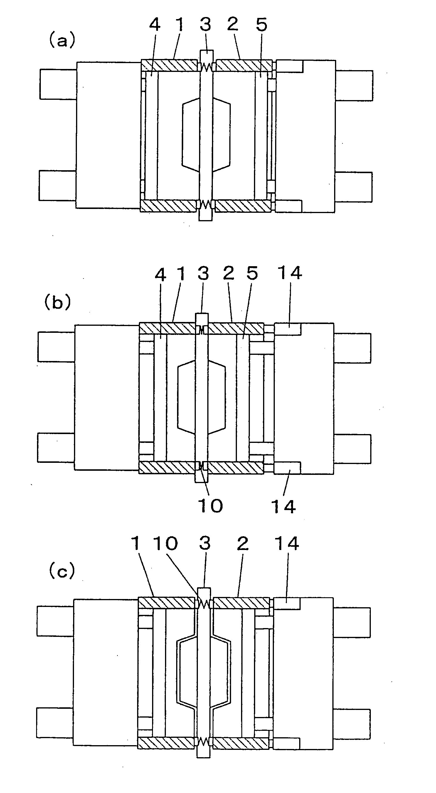
[0056] Below, an embodiment for a method for squeezing foundry sand and a match plate of this invention is explained in detail based on FIGS. 1-4.

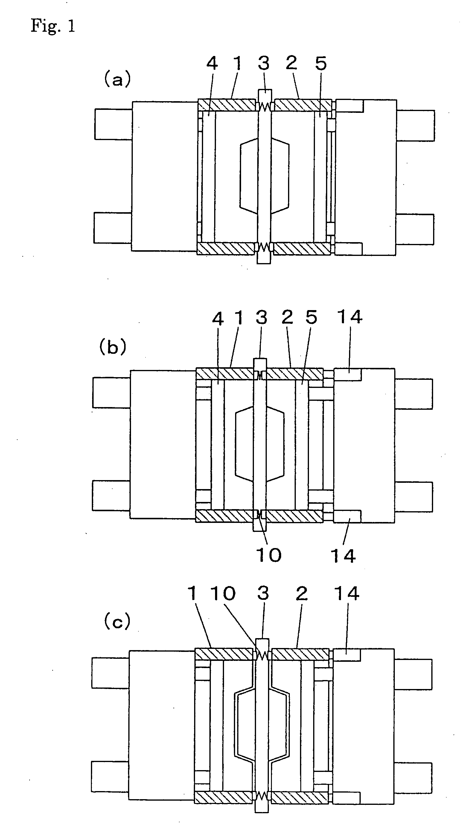
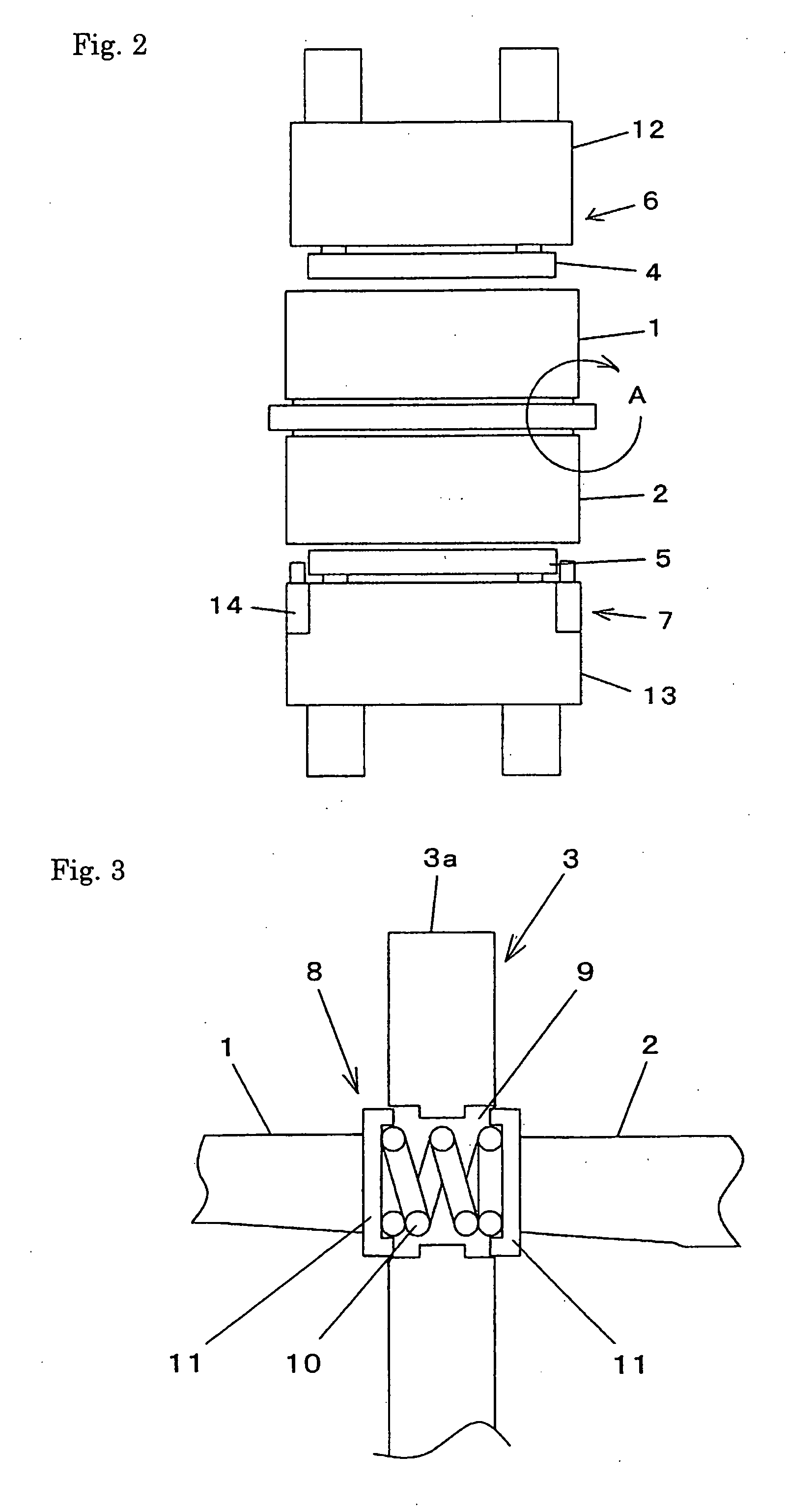
[0057] An expanding and contracting means 8 is disposed at the peripheral border of the pattern portion of the body 3a of the match plate as shown in FIGS. 2-4, wherein the expanding and contracting means 8 can be expanded and contracted by being pressed with end surfaces of an upper and a lower flask 1, 2, which surfaces oppose the match plate 3. As shown in FIG. 3, the expanding and contracting means 8 is comprised of a plurality of compression coil-springs 10, 10 disposed in a plurality of through-holes 9, 9 formed at the body 3a of the match plate, and support members 11, 11 having a frame-like structure to hold the plurality of the compression coil-springs 10, 10 by compressing them at both sides of the coil-springs 10, 10, wherein the support members 11, 11 are mounted on the body 3a of the match plate.

[0058] As shown in FIG. 4, it...

embodiment 2

[0062] Below, an embodiment using another expanding and contracting means is explained based on FIGS. 5-7. The expanding and contracting means 20 is disposed at the peripheral border of the pattern portion of the match plate 21 as shown in FIGS. 5-7, wherein the expanding and contracting means 20 can be expanded and contracted by being pressed with the end surfaces of an upper and a lower flask 1, 2, which surfaces oppose the match plate 21. As shown in FIG. 6, the expanding and contracting means 20 is comprised of a plurality of compression coil-springs 23, 23 disposed in a plurality of through-holes 22, 22 formed at the match plate 21, and support members 24, 24 having a frame-like structure and a U-like configuration at its cross section to. hold the plurality of the compression coil-springs 23, 23 by compressing them at both sides of the coil-springs 23, 23. As shown in FIG. 7, it is possible to dispose a plurality of the compression coil-springs 23, 23 of the expanding and cont...

embodiment 3

[0065] Below, an embodiment using another expanding and contracting means is explained based on FIGS. 8-10. The first expanding and contracting means 32 is disposed at the end surfaces of the upper and the lower flask 30, 31, which surfaces oppose the match plate 21, as shown in FIGS. 8-10, wherein the first expanding and contracting means 32 can be expanded and contracted by being pressed with the end surfaces of an upper and a lower flask 30, 31, which surfaces oppose the match plate 21. As shown in FIG. 9, the first expanding and contracting means 32 is comprised of pins 33, 33 that are slidably disposed in the upper and the lower flask 30, 31 and protrude from the flasks, and a plurality of compression coil-springs 34, 34 to apply the force so that the pins 33, 33 are expanded. The end surfaces of the pins 33, 33 extend toward and contact the end surfaces of the match plate 21. The pins 33, 33 disposed at the first expanding and contracting means 32 contact the four corners of t...


PUM

PropertyMeasurementUnit
molding spaceaaaaaaaaaa
moldingaaaaaaaaaa
hardnessaaaaaaaaaa

Abstract

In a conventional apparatus for molding molds, foundry sand is filled in an upper and a lower molding space defined by a match plate, an upper and a lower flask, and an upper and a lower squeeze plate, and then the foundry sand is squeezed by causing the upper and the lower squeeze plate to further approach each other. However, the hardness and strength near the inner surface that corresponds to the match plate, of an upper and a lower mold made by the conventional apparatus, are not high enough. To solve this problem, in this invention the following method is applied: a method for squeezing foundry sand filled in an upper and a lower molding space, comprising: a step to squeeze the foundry sand by causing the upper and the lower squeeze plate to further approach each other, and a step to squeeze it by causing the pattern portions of the match plate to move to each of the upper and the lower squeeze plate.

Description

TECHNICAL FIELD [0001] This invention relates to a method for squeezing sand and producing a match plate. Particularly, it relates to a method for squeezing the foundry sand filled in an upper and a lower molding space defined by a match plate, an upper and a lower flask, and an upper and a lower squeeze plate. Further, it relates to the match plate and the upper and the lower flask. BACKGROUND OF THE INVENTION [0002] The inventors of this invention have developed the following apparatus for molding a mold: [0003] The apparatus is comprised of an upper and a lower molding space, an aeration mechanism to discharge foundry sand into the molding spaces, and a squeezing mechanism to squeeze the foundry sand, [0004] wherein the upper and the lower molding space are defined by an upper and a lower flask each having intakes disposed at their side walls for foundry sand, a match plate disposed between the upper and the lower flask, and the squeezing mechanism having squeeze plates, which ca...

Claims


Application Information

Patent Timeline
Patent Type & Authority Applications(United States)
IPC IPC(8): B22C15/02
CPCB22C15/02B22C19/02B22C21/00B22D18/02
Inventor HIRATA, MINORUTERABE, TOKIYASAKAGUCHI, KOICHI
Owner SINTOKOGIO LTD
Why Eureka
Try Eureka