Durable Switches and Methods for Using Such

Inactive Publication Date: 2007-10-04
APPLIED INNOVATIVE TECH
View PDF20 Cites 14 Cited by
  • Summary
  • Abstract
  • Description
  • Claims
  • Application Information

AI Technical Summary

Benefits of technology

[0004] Various embodiments of the present invention provide switches that offer one or more features aiding in, among other things, the functionality, durability, accessibility, and/or non-clogging aspects of a switch. Some embodiments of the present invention p

Problems solved by technology

Such switches are susceptible to damage from a number of environmental factors including, for example, corrosion build up on the electric

Method used


Image

  • Durable Switches and Methods for Using Such
  • Durable Switches and Methods for Using Such
  • Durable Switches and Methods for Using Such

Examples


Example

[0023] Various embodiments of the present invention provide switches that offer one or more features aiding in, among other things, the functionality, durability, accessibility, and / or non-clogging aspects of a switch. Some embodiments of the present invention provide switches with an actuator and a field switching element. In such embodiments, the actuator can be open such that obstructions in proximity the actuator can be removed, and in some cases the actuator can be utilized to encourage removal of the obstructions.

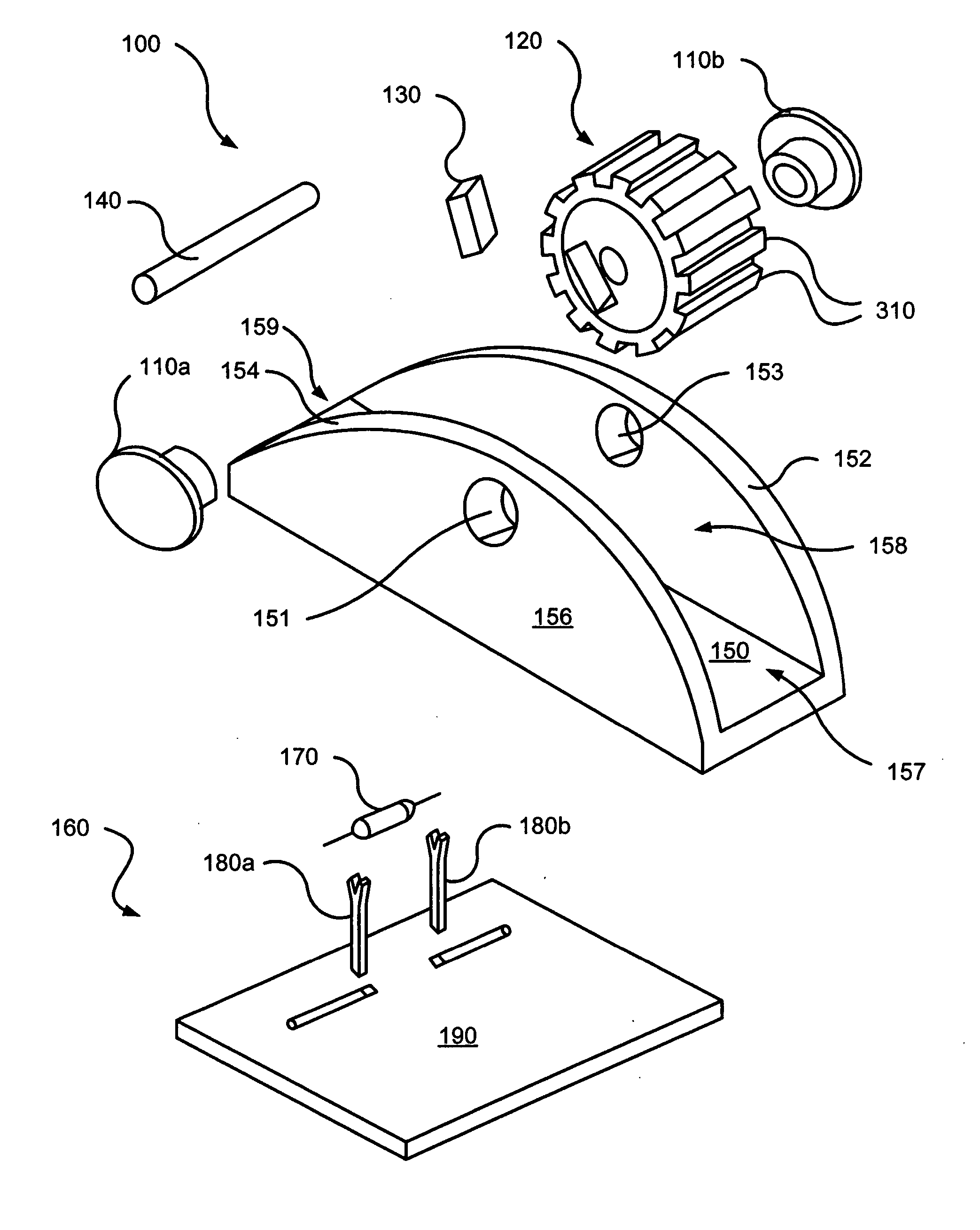
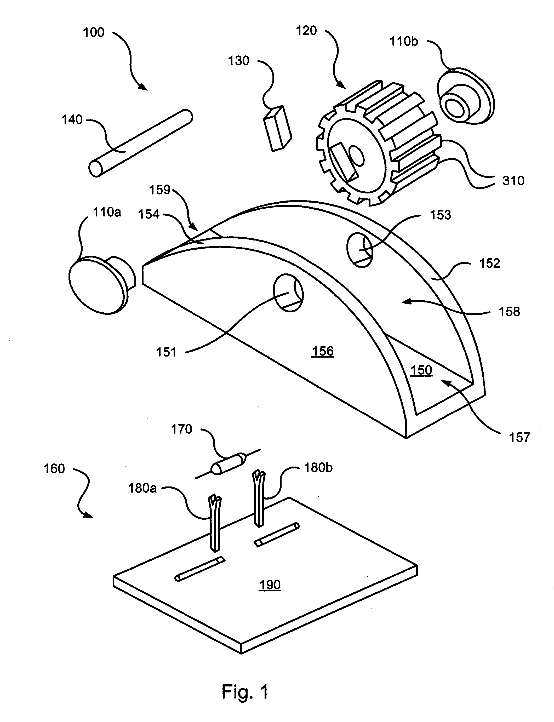
[0024] Referring to FIG. 1, an exploded view of a switch activator 100 and a switching element 160 in accordance with some embodiments of the present invention is depicted. Switch activator 100 includes a switch housing 156 including two opposing sides 152, 154; a channel base 150, and an open channel 158 extending between sides 152, 154 and a distal opening 159 and a proximal opening 157 between the respective distal and proximal ends of sides 152, 154. Switch activ...


PUM


Abstract

Among other things, various durable switches are disclosed that can include a switch housing, an actuator element, and a field element. The switch element can include a channel defined by a channel base, at least one channel side, and at least one open end. The actuator element can be rotatably mounted to the channel side such that rotation of the actuator element causes an outer point of the actuator element to position at a location proximate the channel base. In this position, a passage through the open end is substantially larger than a passage between the outer point of the actuator element and the point proximate the channel base. Further, rotation of the actuator element causes a change in location of the field element that can effectuate switching.

Description

BACKGROUND OF THE INVENTION [0001] Various embodiments of the present invention relate generally to switching technology, and more particularly to durable switches and methods of using such. [0002] Various switches exist for use in a number of different applications. A typical switch includes a mechanical element that is physically moved causing a physical connect / disconnect between two or more electrical contacts. Such switches are susceptible to damage from a number of environmental factors including, for example, corrosion build up on the electrical contacts and obstructions impeding movement of the mechanical element. Seals or other blocking devices have been formed around the mechanical element to limit interference of obstructions with the mechanical element. However, such seals can be costly and in some cases ineffective. [0003] Thus, for the aforementioned reasons and others, there exists a need in the art for advanced systems, apparatus, and methods for switching. BRIEF SUM...

Claims


Application Information

Patent Timeline
IPC IPC(8): H01R33/96
CPCH01H19/03H01H19/115H01H2229/062H01H36/0006H01H2019/146H01H19/14
Inventor YIM, STEVE Y.WONG, MANS
Owner APPLIED INNOVATIVE TECH
Why Eureka
Try Eureka