Battery module system, method of charging battery module and charging type vacuum cleaner

a battery module and vacuum cleaner technology, applied in the direction of cell components, instruments, sustainable manufacturing/processing, etc., can solve the problems of shortened overcharged state, and high voltage of unit cells, and achieve the effect of reducing the cycle life of battery modules and reducing the cost of battery modules

Inactive Publication Date: 2007-10-04
KK TOSHIBA
View PDF7 Cites 50 Cited by
  • Summary
  • Abstract
  • Description
  • Claims
  • Application Information

AI Technical Summary

Benefits of technology

[0022]FIG. 4 is a flowchart showing a control flow to charge using a charging method acco...

Problems solved by technology

A problem arising when batteries are connected in series is variations between unit cells.
There are variations in voltage in a full charge state as a problem leading, particularly, to disorders.
When batteries different in capacity are connected in series or in the condition that the SOCs (state of charging) of them are deviated from each other, unit cells having a voltage higher than the average and unit cells having a voltage lower than the average arise in a full-charged condition of the battery module, the unit cell having high voltage is put into a an overcharged state and is resultantly deteriorated greatly.
As a result, this gives rise to the problem that the cycle life of the battery module is shortened more significantly than the unit cell.
Generally, the coulomb efficiency of charging and discharging is almost 100% in secondary batteries and capacitors using a nonaqueous electrolyte and therefore, unlike the nickel metal-hydride battery, the current bypass function by the battery cannot be expected.
However, even if such a method is adopted, it is difficult to efficiently eliminate variations in the charged voltage of a unit cell because of the following problems.
It is difficult to suppress variations in Zener voltage like the case of producing a battery reduced in ...

Method used


Image

  • Battery module system, method of charging battery module and charging type vacuum cleaner
  • Battery module system, method of charging battery module and charging type vacuum cleaner
  • Battery module system, method of charging battery module and charging type vacuum cleaner

Examples


first embodiment

[0040]A method of charging a battery module according to a first embodiment will be explained.

[0041]The battery module is formed by connecting plural battery units in series. Each of the battery units comprises at least one unit cell. When the battery unit comprises plural unit cells, it is desirable to form one battery unit by connecting unit cells in parallel.

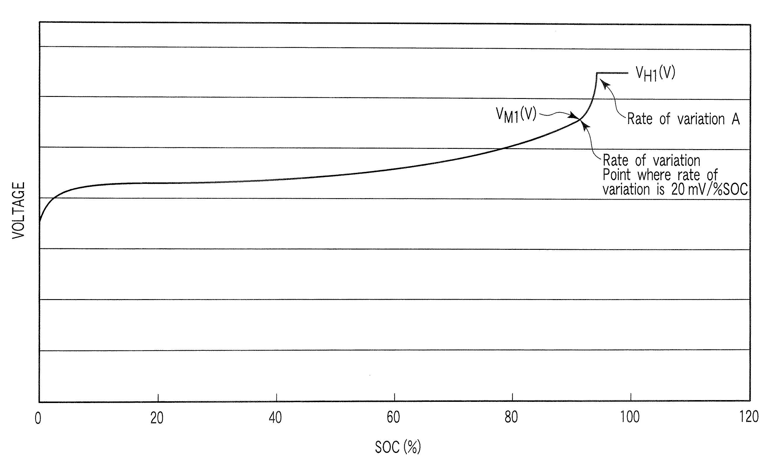
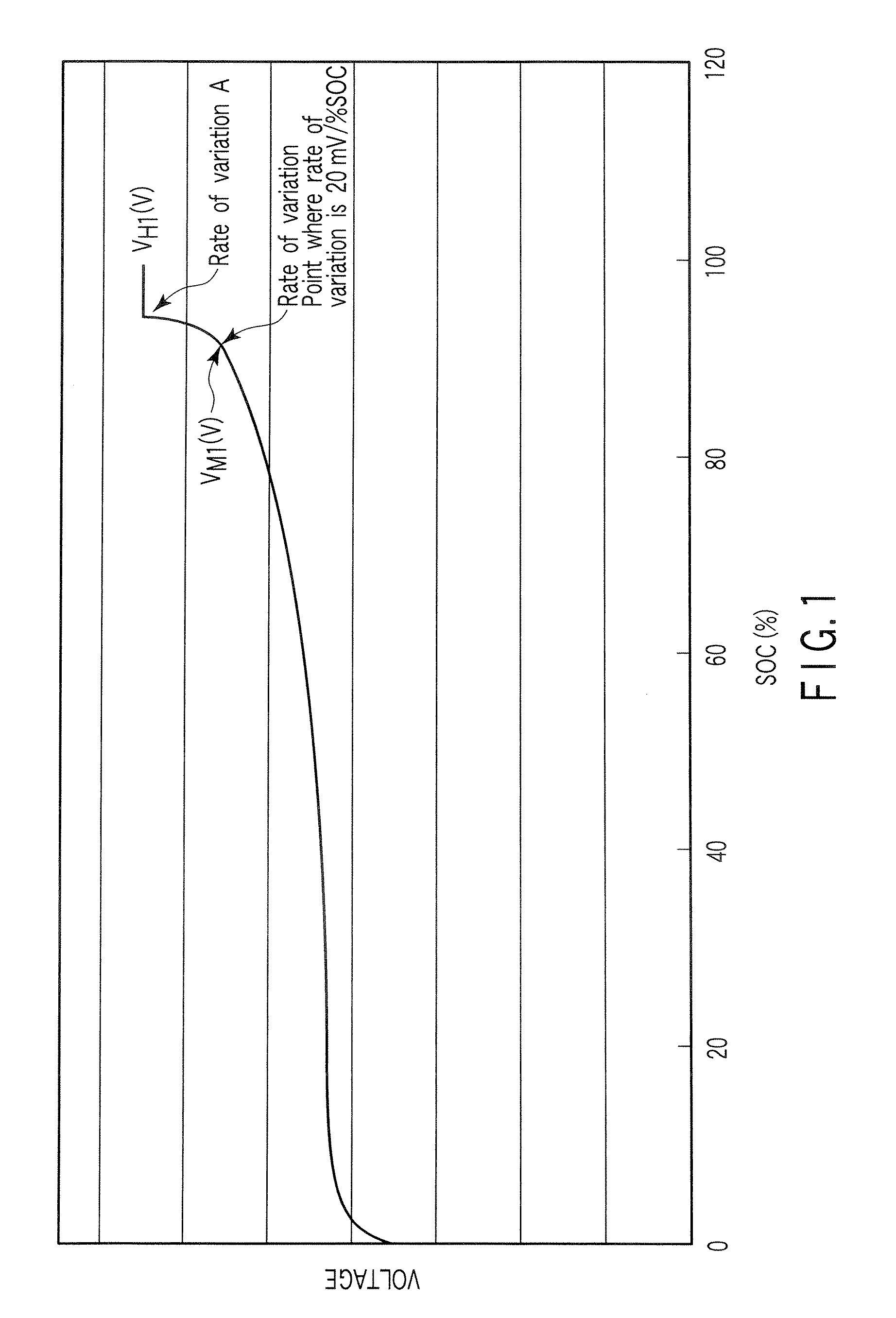
[0042]FIG. 1 shows one example of a charge curve when a nonaqueous electrolyte secondary battery used as a unit cell is charged at a current of 1 C at 25° C. by using a method of charging a battery module according to the first embodiment. Here, 1 C is the current required to discharge a unit cell in one hour and the value of the nominal capacity of a unit cell may be used as the 1 C current for the sake of convenience. In FIG. 1, the abscissa shows the state of charging (SOC) of the nonaqueous electrolyte secondary battery and the ordinate shows the voltage (closed circuit voltage) of the nonaqueous electrolyte secondary bat...

second embodiment

[0052]One example of a battery module system according to a second embodiment of the present invention will be explained in detail.

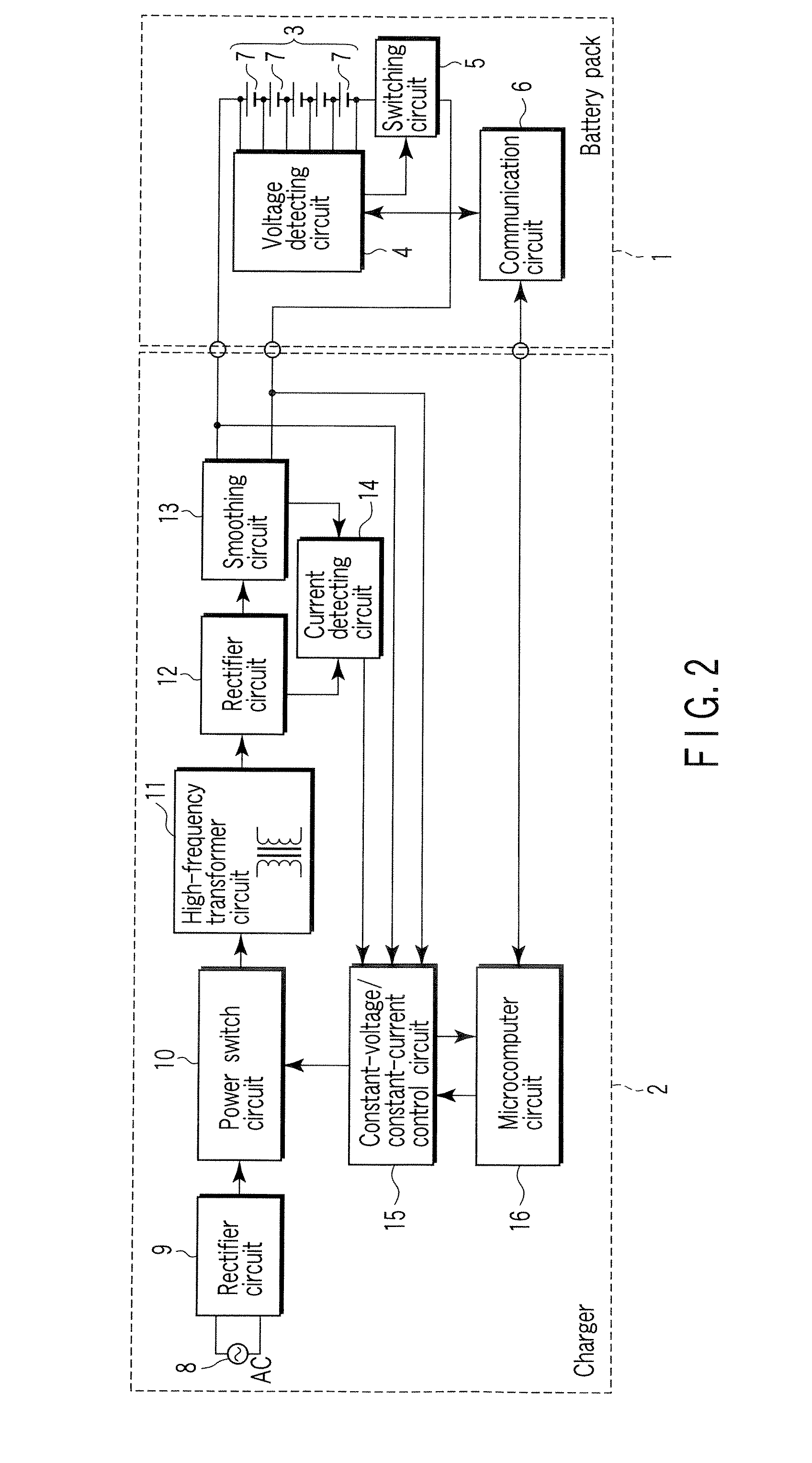
[0053]FIG. 2 is an example of the block diagram of a battery module system according to the second embodiment of the present invention. The battery module system comprises a battery pack 1 and a charger 2. The battery pack 1 comprises a battery module 3 and a protective circuit. The protective circuit contains a voltage detecting circuit 4, a switching circuit (SW circuit) 5 and a communication circuit 6. The battery module 3 comprises plural battery units 7 constituted of a unit cell connected in series. As the unit cell, a nonaqueous electrolyte secondary battery is used. Although the number of series is 5 in FIG. 2, this number may be 2 or more and optional. However, if the number of series is too large, it is difficult to detect the voltage using one voltage detecting circuit and therefore, the circuit is complicated. Therefore, the number of series ...

third embodiment

[0119]It is desirable for the battery module system according to the second embodiment of the present invention to be used in the field requiring the large current performance and the charge-discharge cycle performance. To be more specific, it is desirable for the battery module system according to the second embodiment of the present invention to be used in the power source for a digital camera and for the vehicles such as the hybrid electric automobiles having two to four wheels, electric automobiles having two to four wheels, the electric mopeds, and the charging type vacuum cleaner. It is preferable to be used for the vehicles.

[0120]A vehicle according to a third embodiment of the present invention comprises the battery module system according to the second embodiment. The vehicle noted above includes, for example, a hybrid electric automobile having 2 to 4 wheels, an electric automobile having 2 to 4 wheels, and an electric moped. FIGS. 10 to 15 show various type of vehicles ha...


PUM


Abstract

A battery module system includes a battery module and a control member. The battery module comprises battery units are connected in series. Each of the battery units comprises a unit cell having a voltage variation rate A (mV/% SOC) at a full charge voltage VH1 (V) is larger than 20 (mV/% SOC), which is a value obtained when the unit cell is charged at a current of 1 C at 25° C. The control member controls current to a current I1 until a maximum value Vmax (V) among the voltage of each unit cell reaches the full charge voltage VH1 (V) and then controls a voltage of the battery module to a voltage V2 (V) given by the following equation (1):
V2=VH2×n  (1)

Description

CROSS-REFERENCE TO RELATED APPLICATIONS[0001]This application is based upon and claims the benefit of priority from prior Japanese Patent Application No. 2006-096001, filed Mar. 30, 2006, the entire contents of which are incorporated herein by reference.BACKGROUND OF THE INVENTION[0002]1. Field of the Invention[0003]The present invention relates to a battery module system, a charging type vacuum cleaner using the battery module system and a method of charging the battery module.[0004]2. Description of the Related Art[0005]Secondary batteries having high energy densities are developed and utilized as power sources for miniature information devices such as cellular telephones and portable personal computers (PCs). These secondary batteries are used in such a manner that the number of secondary batteries (unit cell) constituting a battery module and the way of combining series-connection and parallel-connection are varied according to voltage and current required for each device. Becau...

Claims


Application Information

Patent Timeline
IPC IPC(8): H02J7/00H01M2/18H01M4/02H01M4/131H01M4/485H01M4/58H01M4/66H01M10/05H01M10/0525H01M10/0583H01M10/0585H01M10/44
CPCH01M4/131H01M4/485H01M4/661H01M10/052H01M10/0525Y02T10/7055H01M2004/021H02J7/0022Y02E60/122Y02T10/7011H01M10/441Y02T10/70Y02E60/10H02J7/0014Y02P70/50H02J7/0013
Inventor TATEBAYASHI, YOSHINAOINAGAKI, HIROKIHARADA, YASUHIROTAKAMI, NORIO
Owner KK TOSHIBA
Why Eureka
Try Eureka