

Liquid crystal display device
a display device and liquid crystal technology, applied in the direction of instruments, static indicating devices, etc., can solve the problems of lowering the efficiency of light utilization, affecting the viewing experience of movies, and affecting the viewing experience of films, so as to achieve superior display contrast and improve movie visibility.
- Summary
- Abstract
- Description
- Claims
- Application Information
AI Technical Summary
Benefits of technology
Problems solved by technology
Method used
Image

Examples
modification 1
(2-10-2) Modification 1
[0180] As described in conjunction with FIG. 6, the gate signal lines G are selected in sequence from the first (ODD 1) to 400th (EVEN 200) signal line. However, the embodiment is not limited thereto. For example, it is also possible to select the odd numberth gate signal lines G (ODD 1 to ODD 200), in the period of 1F / 8, and select the even numberth gate signal lines G (EVEN 1 to EVEN 200) in the subsequent period of 1F / 8. The video data or the black voltages corresponding to the selected pixel rows are applied to the source signal lines S in sequence. The polarity to be applied to the source signal lines S is the same during the period of 1F / 8. Therefore, the power consumption of the gate source driver IC31 can be reduced. Generation of the flicker can easily be restrained.
[0181] In the embodiment shown above, although there is an effect to achieve both the reduction of the power consumption and the restraint of the flicker, there is a case in which lateral...
modification 2
(2-10-3) Modification 2
[0183] As shown in FIG. 10, it is also possible to invert the polarity of the common voltage signal VCOM in the video signal holding periods c1, c2. As shown in FIG. 10, by inverting the polarity of the common voltage signal VCOM applied to the opposed electrodes 362, the inversion cycles match and hence the luminance inclination and the flicker may be reduced. The polarity of the video signals or the black voltage to be applied to the source signal lines S is inverted so as to match the polarity of the common voltage.
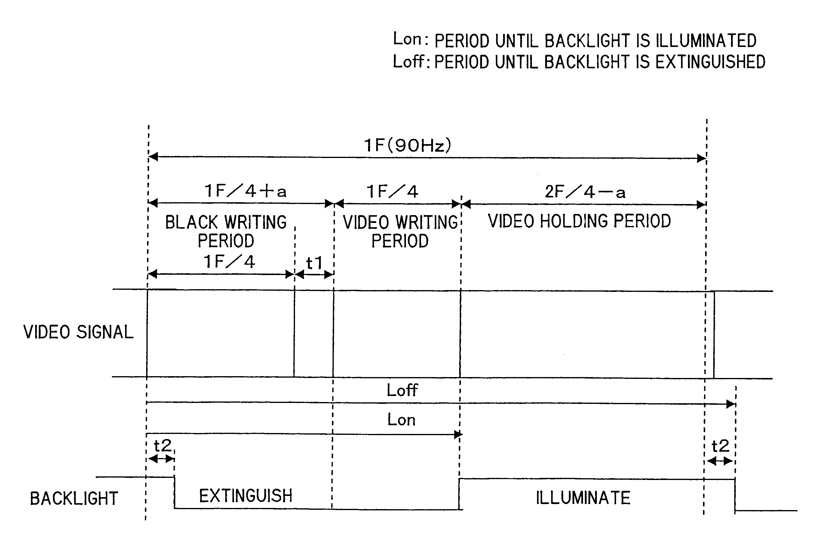
[0184] In FIG. 10, the backlight 18 is illuminated corresponding to the periods c1, c2 of the respective frames. The backlight 18 is extinguished during the periods “a” as the black writing periods and the periods “b” as the video signal writing period.
[0185] As shown in FIG. 10, the common voltage signal is VCOM=VcH in the periods “a” and “b” in the first frame (first F). The common voltage signal is VCOM=VcL in the period c1 as the video hold...
modification 3
(2-10-4) Modification 3
[0189]FIG. 11 shows a modification of FIG. 10. In FIG. 11 as well, the backlight 18 is illuminated corresponding to the periods c1 and c2 of the respective frames. The backlight 18 is extinguished in the periods “a” as the black writing period and the period “b” as the video signal writing period.
[0190] As shown in FIG. 11, the common signal is VCOM=VcH in the period “a” as the black writing period of the first frame (the first F). The common signal is VCOM=VcL in the period “b” as the subsequent video writing period and the period “c1” which is the video holding period. The period “c2” is the common signal VCOM=VcH in the period c2. That is, the polarity of the common signal is inverted in the black writing period and the video writing period, and the polarity of the common signal is also inverted in the video holding period. The lengths of the period “a” of the black writing period and the period “b” of the video writing period match (substantially the same...
PUM
 Abstract
Description
Claims
Application Information