
Battery contacts for an in-vivo imaging device

a technology of in-vivo imaging and battery contacts, which is applied in the direction of coupling device connections, cell components, television systems, etc., can solve the problems of in-vivo imaging devices that may endure turbulence, vibration and temperature changes, and the disconnection of contacts, so as to reduce the amount of space taken up

Active Publication Date: 2007-10-04
GIVEN IMAGING LTD
View PDF15 Cites 135 Cited by
  • Summary
  • Abstract
  • Description
  • Claims
  • Application Information

AI Technical Summary

Benefits of technology

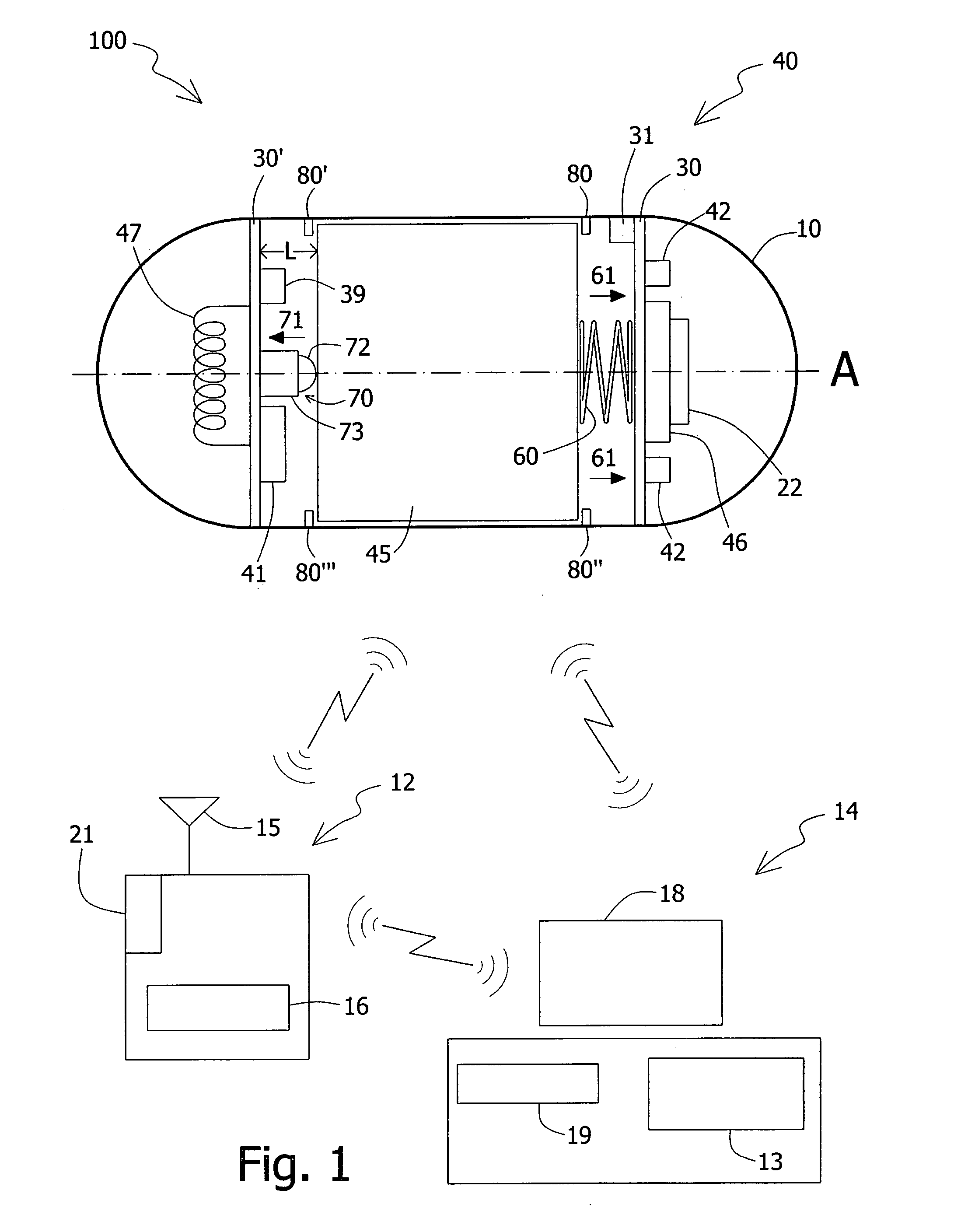
[0008] According to one embodiment of the present invention, an example for economizing space usage may be by employing battery contacts configured to occupy a minimum of space within the in-vivo imaging device and circuit board. For example, according to one embodiment of the present invention a rigid section of a circuit board may support both a transmitter / receiver and a battery contact, and thus decrease the number of rigid and flexible sections of the circuit board. Efficient and economized circuit board setup may enable circuit board folding into smaller sizes which may take up less space, and thus may provide for smaller sized in-vivo devices or for more usable space within an in vivo device.
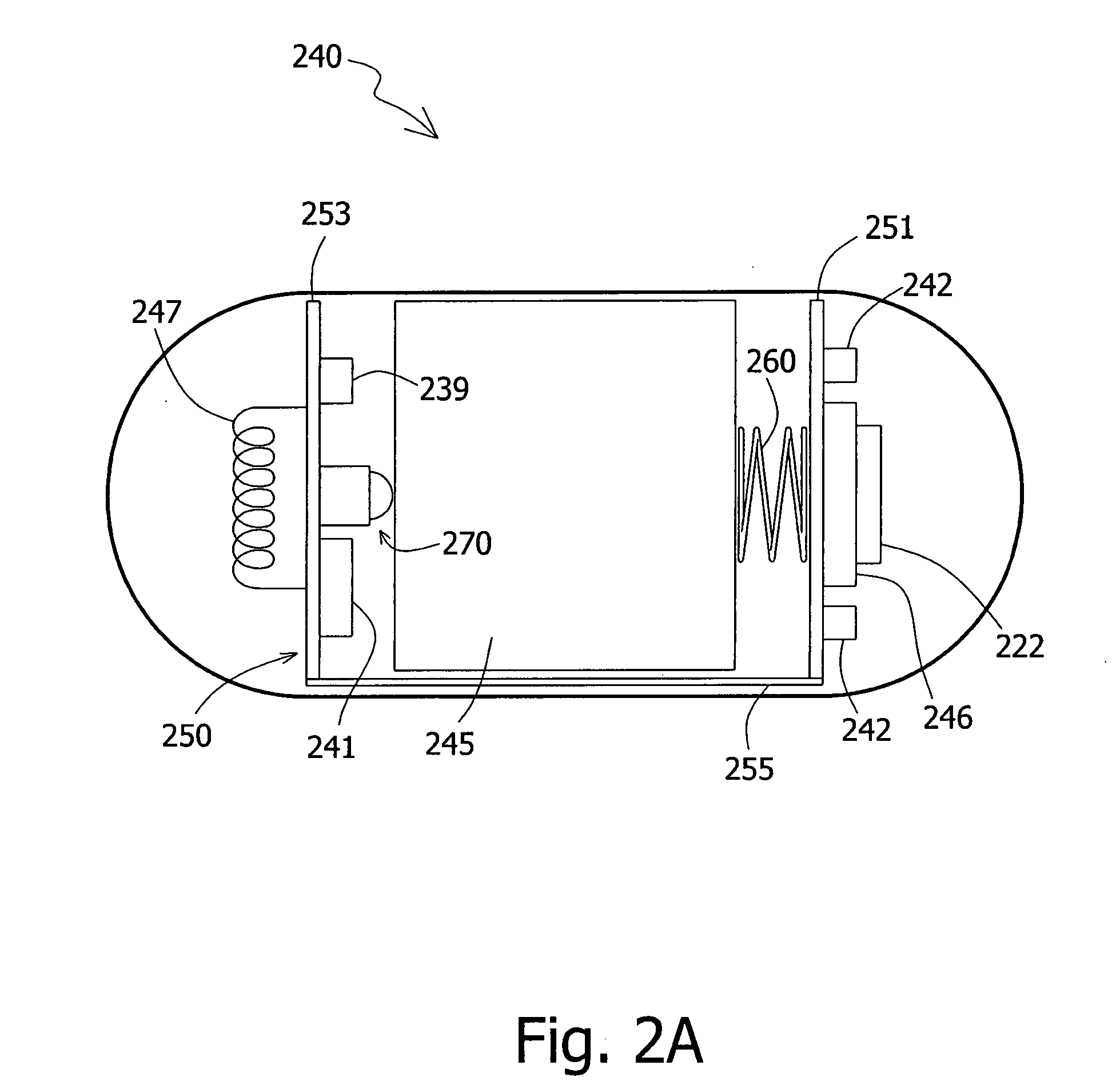
[0010] According to some embodiments of the present invention, the battery contacts include, for example a push-button contact, a ‘pin button and spring’ contact or a spring biased plunger contact, a wire or a thin-sheet strip or other suitable battery contact. According to some embodiments the battery contacts may be integrated or embedded, for example, within a rigid portion and / or the flexible portion of the circuit board. According to some embodiments of the present invention the battery contact may be combined with or attached to other elements in the in vivo imaging device so as to possibly reduce the amount of space taken up by it.

Problems solved by technology

During the movement of the in-vivo imaging device within and outside a human body, the in-vivo imaging device may endure conditions such as turbulence, vibrations and temperature changes.
Such occurrences may cause disconnection between contacts, such as battery contacts, battery and / or electrical circuits or electrical components of the in-vivo imaging device.

Method used


Image

  • Battery contacts for an in-vivo imaging device
  • Battery contacts for an in-vivo imaging device
  • Battery contacts for an in-vivo imaging device

Examples


Embodiment Construction

[0029] In the following description, various aspects of the present invention will be described. For purposes of explanation, specific configurations and details are set forth in order to provide a thorough understanding of the present invention. However, it will also be apparent to one skilled in the art that the present invention may be practiced without the specific details presented herein. Furthermore, well known features may be omitted or simplified in order not to obscure the present invention.

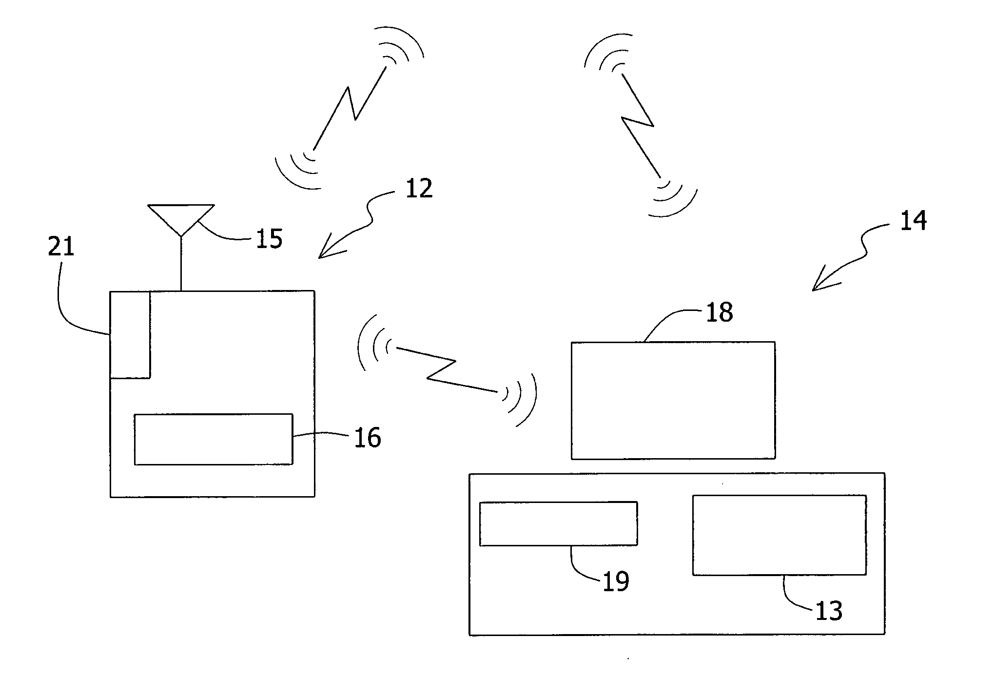
[0030] Reference is made to FIG. 1, which shows a schematic diagram of an in-vivo imaging system 100 according to one embodiment of the present invention. The in-vivo imaging system 100 may include an in-vivo imaging device 40 having, for example an imager 46, for capturing images, an optical system 22, an illumination source(s) 42 such as white LEDs (Light Emitting Diode), OLEDs (Organic LED) or other illumination sources, for illuminating the body lumen, a power source such as a batt...


PUM


Abstract

The invention provides an in vivo imaging device, the device comprising a first support having thereon a first battery contact, a second support having thereon a second battery contact, a battery disposed between the first support and the second support such that the battery is in contact with the first battery contact and with the second battery contact, wherein the first battery contact is a spring and the second battery contact comprises a pin to contact the battery and a housing for the pin and a battery stopper placed between the battery and the first or second support.

Description

CROSS REFERENCE TO RELATED APPLICATIONS [0001] This application claims the benefit of U.S. Provisional Application Ser. No. 60 / 785,992, filed on Mar. 27, 2006, and U.S. Provisional Application Ser. No. 60 / 787,698, filed on Mar. 31, 2006, which is / are incorporated in their entirety herein by reference.FIELD OF THE INVENTION [0002] The present invention relates generally to an in-vivo imaging system suitable for imaging the gastrointestinal (GI) tract or other body lumens. In particular, it is related to battery contacts for an in-vivo imaging device. BACKGROUND OF THE INVENTION [0003] Known devices may be helpful in providing in-vivo imaging. Autonomous in-vivo imaging devices, for example in-vivo imaging devices, such as swallowable or ingestible capsules or other devices may move through a body lumen, imaging as they move along. Some of these devices are battery operated and use a wireless connection to transmit image data. [0004] In some in vivo devices, such as ingestible imaging...

Claims


Application Information

Patent Timeline
IPC IPC(8): H04N7/18H01M2/10H05K7/00
CPCA61B1/041A61B1/042H05K1/189H01M2/1066H01R13/2421H01M2/1055Y02E60/10H01M50/213
Inventor KHAIT, SEMIONGILAD, ZVIKAMANN, CHEN
Owner GIVEN IMAGING LTD
Learn More