
Surveillance network for unattended ground sensors

a technology for surveillance networks and sensors, applied in the direction of instruments, electric signalling details, burglar alarms, etc., can solve the problems of large false positives, delay in information flow, and large amount of irrelevant data buried in important data, so as to reduce false positives

Inactive Publication Date: 2007-10-11
BECKSTED ALBERT MICHAEL +1
View PDF8 Cites 59 Cited by
  • Summary
  • Abstract
  • Description
  • Claims
  • Application Information

AI Technical Summary

Benefits of technology

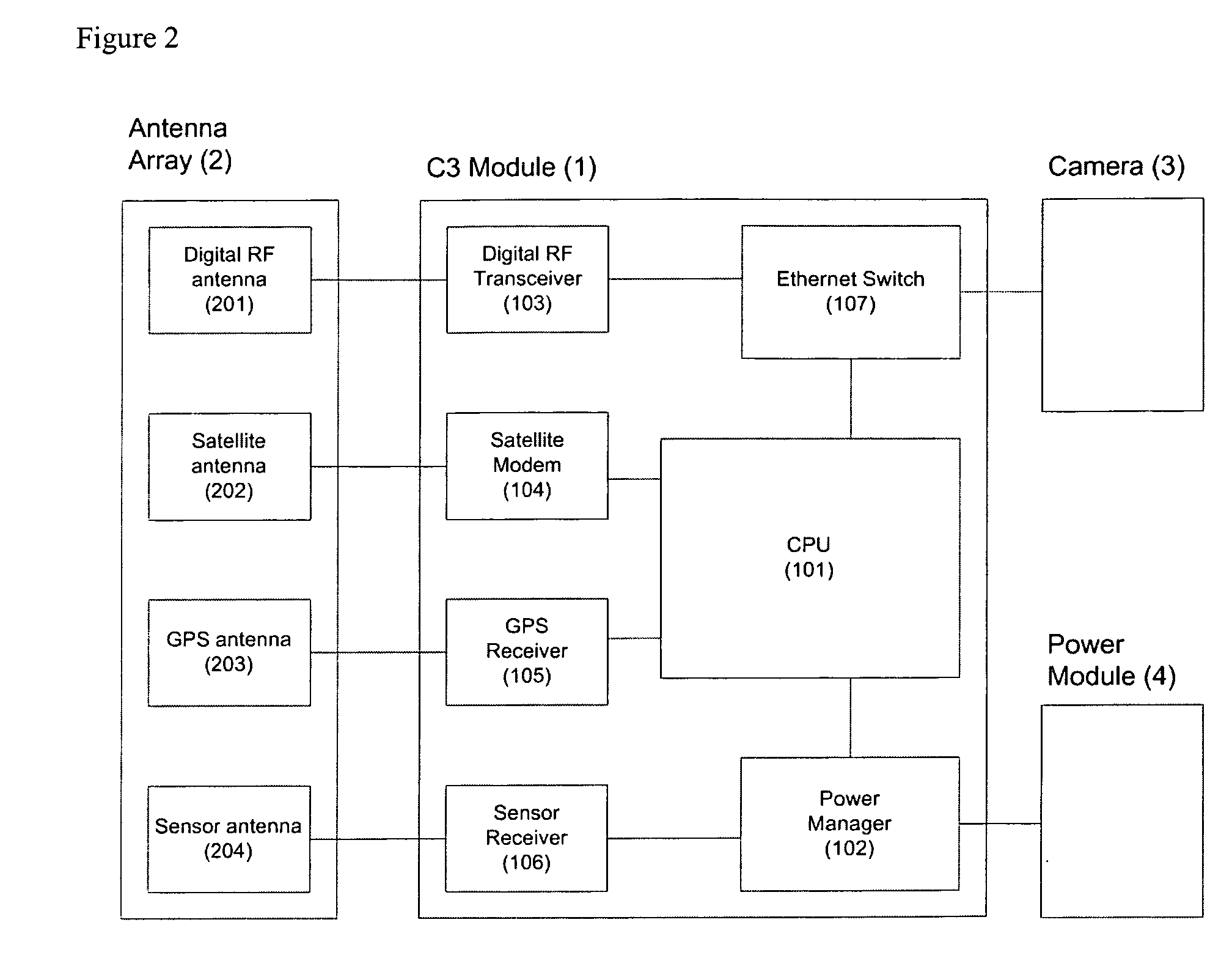
[0023] The system according to the invention may include a module, one or more sensors with a camera, a server, and a user interface device. The system is connected via, a distributed computing network. The module allows the system to discriminate sensor events by processing the raw data and making sense of it. Therefore, the data is transmitted selectively, making best use of limited communication channels. A communication channel with global coverage allows total data integration for high level responding personnel, and digital day / night cameras allows for constant visual confirmation.
[0024] Advantages of the present invention include the conversion of raw data into meaningful information to give full situational awareness to responding personnel. Mission critical data is accessible concurrently to multiple stations in the responder chain. Visual confirmation of the situation is provided to reduce false positives. A global footprint allows for deployment anywhere in the world. Near real-time alerts allow quick response or prevention.

Problems solved by technology

However, these systems do not differentiate the sensor data collected, resulting in important data being buried in huge amounts of irrelevant data and large numbers of false positives.
Such systems cause delay of the information flow and do not provide visual confirmation of the remote site that is to be monitored.
Other common problems with current surveillance systems include the isolation of each sensor array (i.e. they are not networked with the other arrays).
This results in limited situational awareness for the responding personnel.
Also the resulting data is typically raw and unprocessed, resulting in large amounts of unnecessary data and false positives.
Furthermore there is no visual confirmation, further limiting situational awareness.
There are also typically long delays in information flow to responding personnel resulting in an inability to effectively respond to the situation.

Method used


Image

  • Surveillance network for unattended ground sensors
  • Surveillance network for unattended ground sensors
  • Surveillance network for unattended ground sensors

Examples


Embodiment Construction

[0046] Note in this document the terms “module” and “C3Module” are used interchangeably.

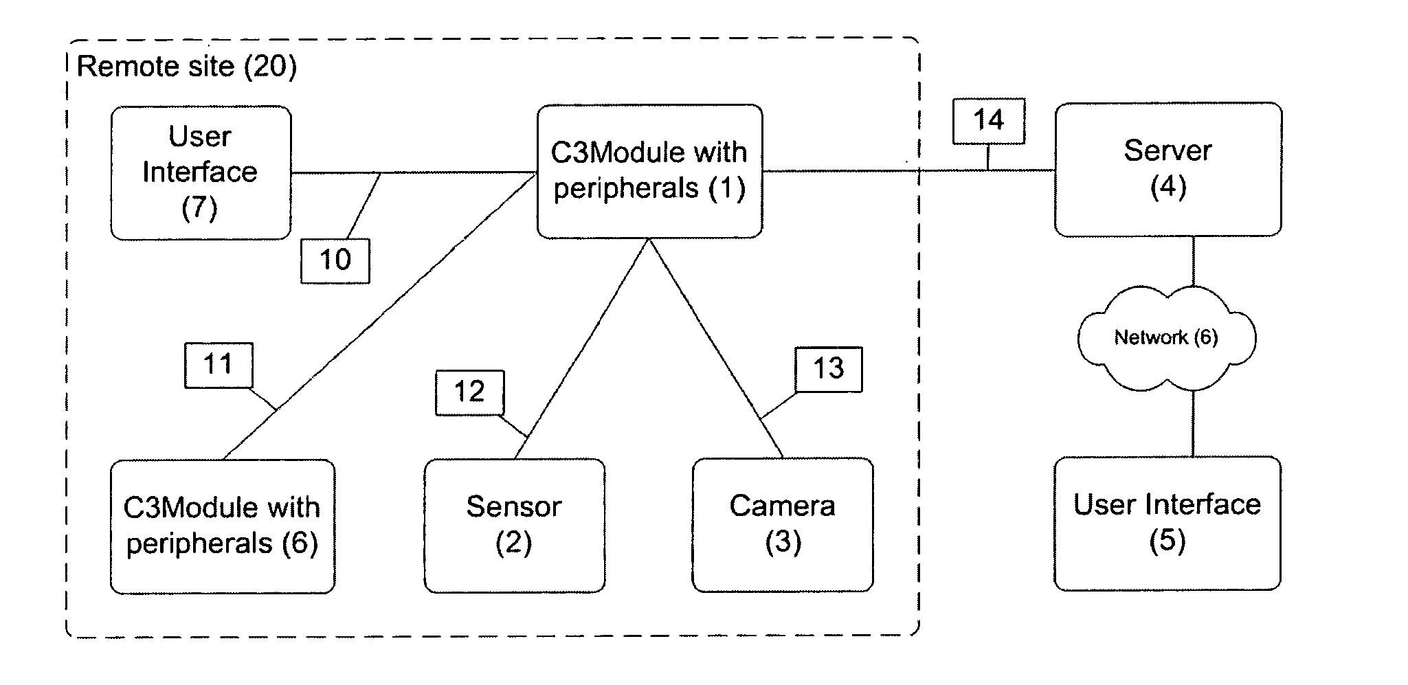
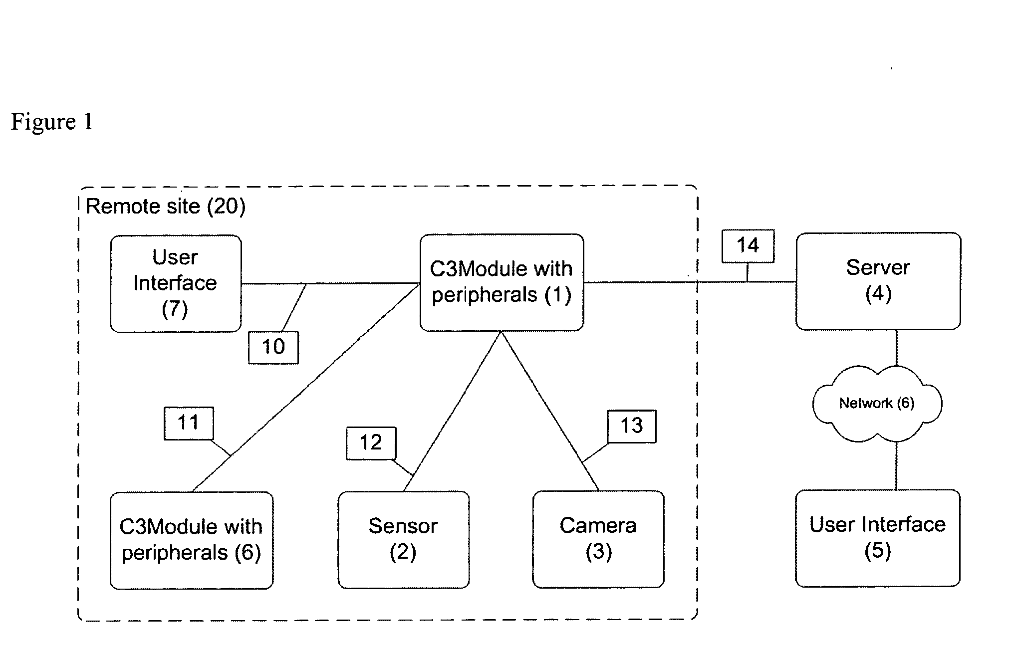
[0047] As seen in FIG. 1, a system according to the invention is used to monitor a remote site 20, for example a pipeline, a power plant, a border or other location. At remote site 20 is deployed at least one module 1, at least one camera 3, at least one sensor 2, and optionally, other devices. Server 4 is located at a central station anywhere. Responding personnel can access the stored data at module 1 or be notified of an event directly from module 1 through connection 10 to user interface 7 or indirectly from module 1 to server 4 and network 6 to user interface 5 through connection 14.

[0048] Sensors 2 are preferably covertly deployed in a manner to protect an asset or monitor a perimeter or other object at remote site 20. If an intruder enters remote site 20, sensor 2 sends a signal to module 1 through a communication channel 12. Communication channel 12 is preferably wireless, such as a dig...


PUM


Abstract

A method for responding to a sensor event is provided, comprising the steps of: (a) recognizing and analyzing a sensor event, and declaring an alarm condition; (b) taking a picture, storing the picture, and transmitting the picture to a central server; (c) notifying subscribers with a message that can contain visual confirmation and other data describing the alarm event; and (d) interrogating a module, downloading event data and images.

Description

[0001] This application claims benefit of U.S. Provisional Patent Application No. 60 / 612,154 filed Sep. 23, 2004, which is hereby incorporated by reference.FIELD OF THE INVENTION [0002] The present invention relates to surveillance networks for unattended ground sensors and more particularly to methods and systems for remote surveillance, transmission, recording and analysis of images and sensor data. BACKGROUND OF THE INVENTION [0003] Many different forms of such surveillance systems are known. The sensors in such systems may be connected through a wireless link to a central data collector. However, these systems do not differentiate the sensor data collected, resulting in important data being buried in huge amounts of irrelevant data and large numbers of false positives. Such systems cause delay of the information flow and do not provide visual confirmation of the remote site that is to be monitored. [0004] Other common problems with current surveillance systems include the isolat...

Claims


Application Information

Patent Timeline
IPC IPC(8): G08B19/00G08B1/08
CPCG08B13/19695
Inventor BECKSTED, ALBERT MICHAELSTOKES, ALLAN
Owner BECKSTED ALBERT MICHAEL
Learn More