Patch panel cover mounted antenna grid for use in the automatic determination of network cable connections using RFID tags

a technology of automatic determination and antenna grid, which is applied in the direction of burglar alarm mechanical actuation, burglar alarm by hand-portable article removal, instruments, etc., can solve the problems of inability to fix problems or provide new services, failure to solve problems, and insufficient knowledge of complex networks such as telecommunication networks or sophisticated computer networks

Active Publication Date: 2007-10-11
LUCENT TECH INC
View PDF14 Cites 40 Cited by
  • Summary
  • Abstract
  • Description
  • Claims
  • Application Information

AI Technical Summary

Benefits of technology

[0010] We have recognized that an RF antenna grid design in which the antenna array is installed on a patch panel cover, rather than on the patch panel itself, advantageously allows for the retrofitting of an RF antenna grid on existing patch panel based systems without disrupting network operation. In accordance with the principles of the present invention, therefore, an apparatus for determining connectivity between one or more device ports thereof and one or more cable ends having corresponding RFID tags atta

Problems solved by technology

The management of complicated networks such as telecommunications networks or sophisticated computer networks is tremendously expensive.
A substantial portion of this cost arises from incomplete, incorrect or ambiguous knowledge about a network.
For example, a telecommunications network operator may not have an accurate record of how network switches are configured, leading to failed attempts to fix problems or provision new services.
However, a more fundamental ambiguity arises at the physical level of network cable management.
However, it is very difficult to maintain an accurate record of exactly which cable is connected to which port of a given piece of equipment (e.g., a patch panel of a telecommunications switch), since the cables may so easily be connected, disconnected, and reconnected.
In a large telecommunications or computer network system, it is an extremely expensive proposition to keep track of every cable, where it is, where it runs, and which port on a given piece of equipme

Method used


Image

  • Patch panel cover mounted antenna grid for use in the automatic determination of network cable connections using RFID tags
  • Patch panel cover mounted antenna grid for use in the automatic determination of network cable connections using RFID tags
  • Patch panel cover mounted antenna grid for use in the automatic determination of network cable connections using RFID tags

Examples


Embodiment Construction

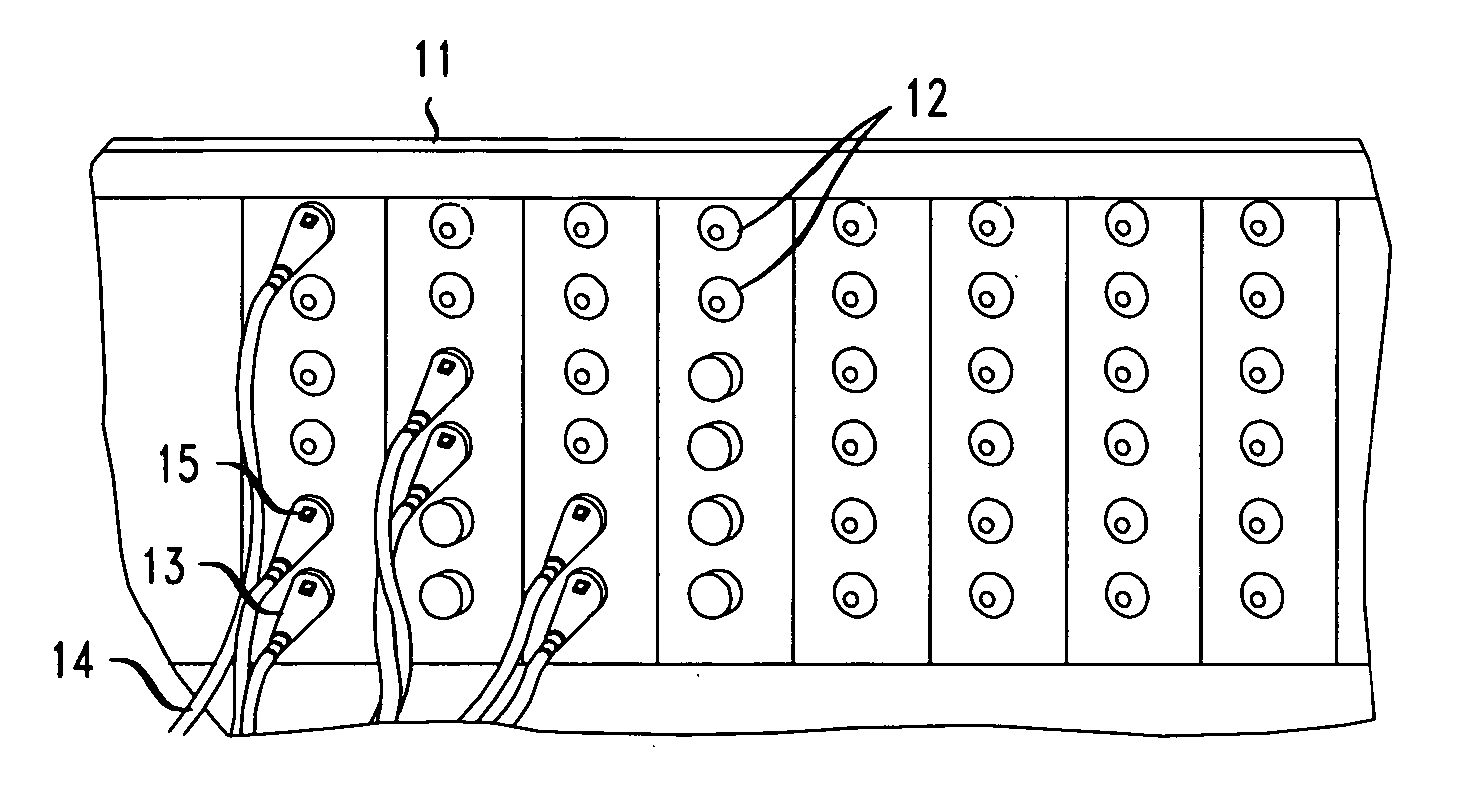
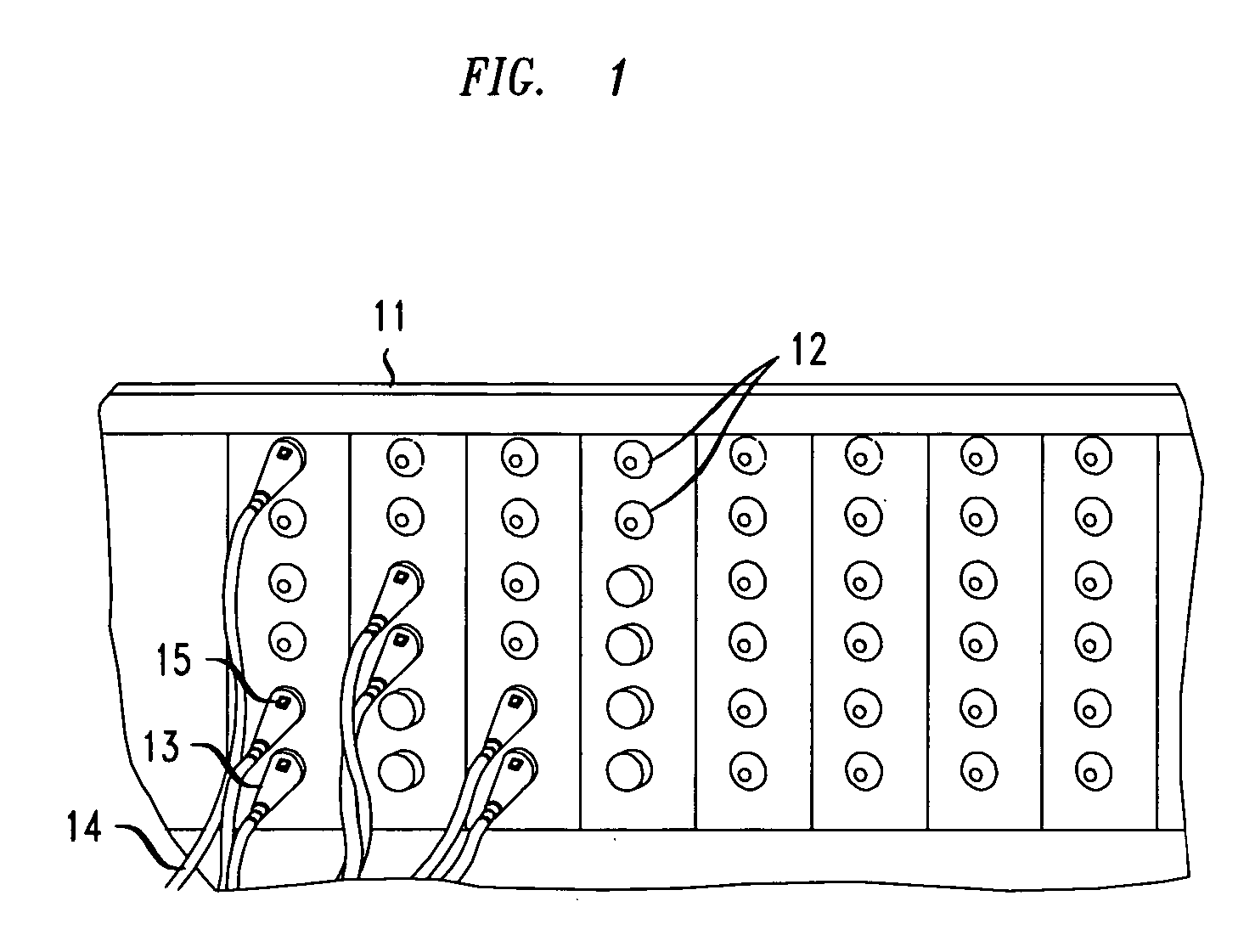
[0016] In accordance with the principles of the present invention, an RF antenna grid array is installed on a patch panel cover in such a manner as to enable the sensing of RFID tags attached to cable ends which have been plugged into device ports on a patch panel, when the patch panel cover is affixed to the patch panel. In particular, the RF antennas advantageously comprise protruding portions thereof to enable such sensing of the RFID tags. Note that as used herein, the term “patch panel” encompasses any physical object which comprises a plurality of device ports, each of which is capable of having a cable end attached thereto; and the term “patch panel cover” encompasses any physical object which is capable of being physically attached or connected to a patch panel.

[0017] In accordance with one illustrative embodiment of the invention, a patch panel comprising a rectangular array of device ports has a patch panel cover attached thereto, wherein a RF antenna grid comprising a pl...


PUM


Abstract

An RF antenna grid design in which the antenna array is installed on a patch panel cover allows for the retrofitting of an RF antenna grid on existing patch panel based systems without disrupting network operation. An apparatus for determining connectivity between device ports on a patch panel and cable ends having corresponding RFID tags attached thereto comprises a patch panel having a plurality of device ports and a patch panel cover comprising a plurality of RFID antennas, where each of the RFID antennas comprises one or more protruding portions thereof, each of the protruding portions of the RFID antennas being in close physical proximity to one or more of the plurality of device ports when the patch panel cover is positioned in a fixed positional relationship to the patch panel (e.g., when the patch panel cover is “attached” to the patch panel).

Description

FIELD OF THE INVENTION [0001] The present invention relates generally to the field of Radio Frequency Identification (RFID) systems and more particularly to the use of RFID techniques for the automatic determination of network cable connections. BACKGROUND OF THE INVENTION [0002] The management of complicated networks such as telecommunications networks or sophisticated computer networks is tremendously expensive. A substantial portion of this cost arises from incomplete, incorrect or ambiguous knowledge about a network. For example, a telecommunications network operator may not have an accurate record of how network switches are configured, leading to failed attempts to fix problems or provision new services. This lack of knowledge can in some instances be remedied by polling the networking equipment to determine its actual settings. [0003] However, a more fundamental ambiguity arises at the physical level of network cable management. Network cables may be added, removed or moved b...

Claims


Application Information

Patent Timeline
IPC IPC(8): G08B13/14G08B21/00H01R3/00
CPCH01Q1/2208H04Q1/149H01Q1/2216
Inventor FLASTER, MICHAEL E.MARTIN, CLIFFORD E.NG, WEE TECKTRAN, CUONG
Owner LUCENT TECH INC
Why Eureka
Try Eureka