

Lighting Process And Mechanism
Patent Information
- Authority / Receiving Office
- US · United States
- Current Assignee / Owner
- RAIN BIRD EURO R L
- Publication Date
- 2007-10-11
- Estimated Expiration
- Not applicable · inactive patent
Smart Images
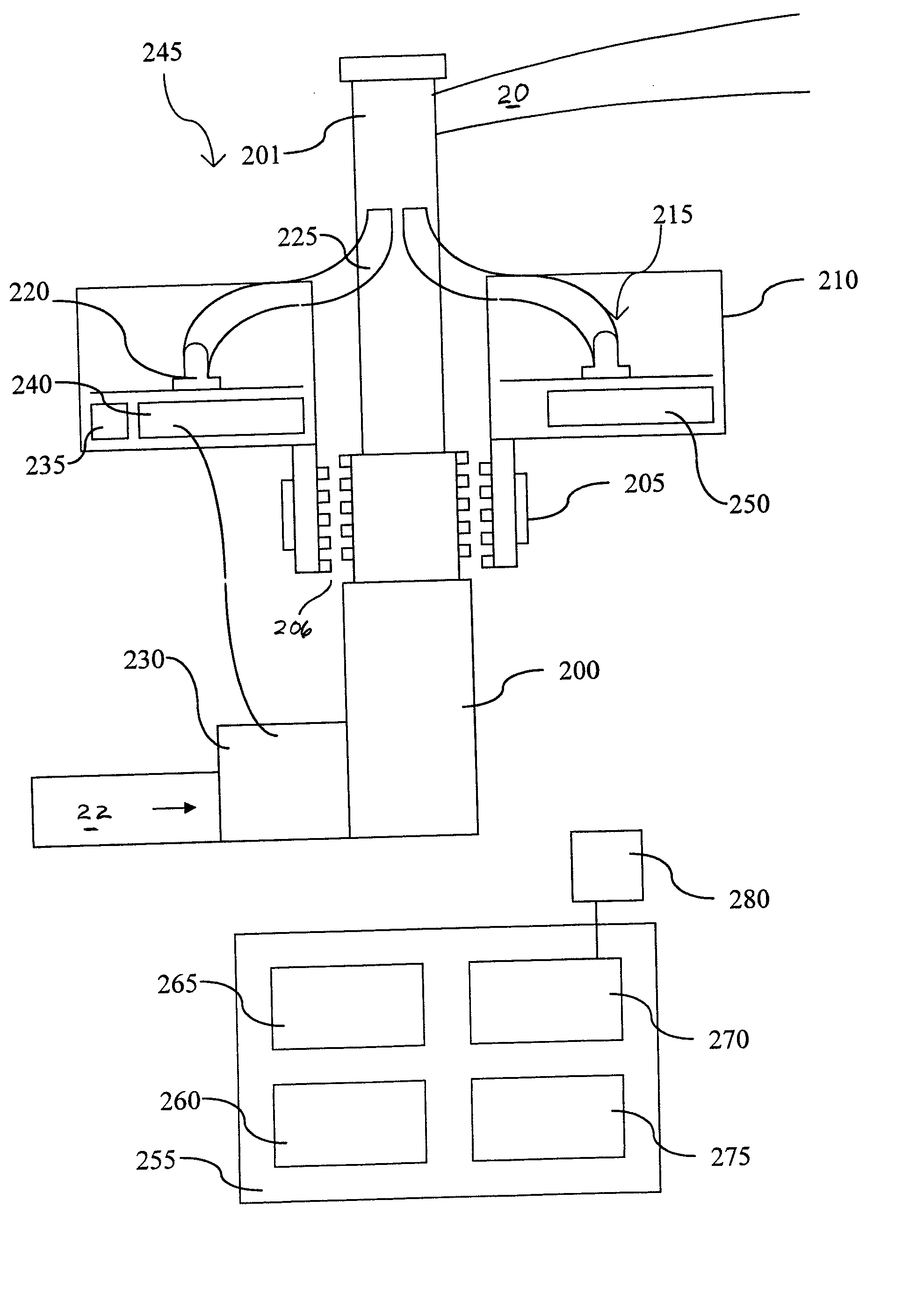
Figure 1 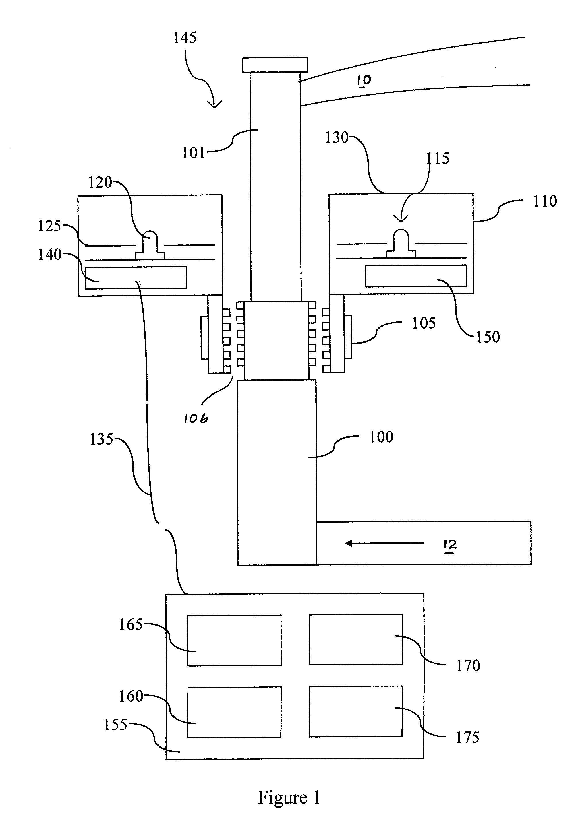
Figure 2 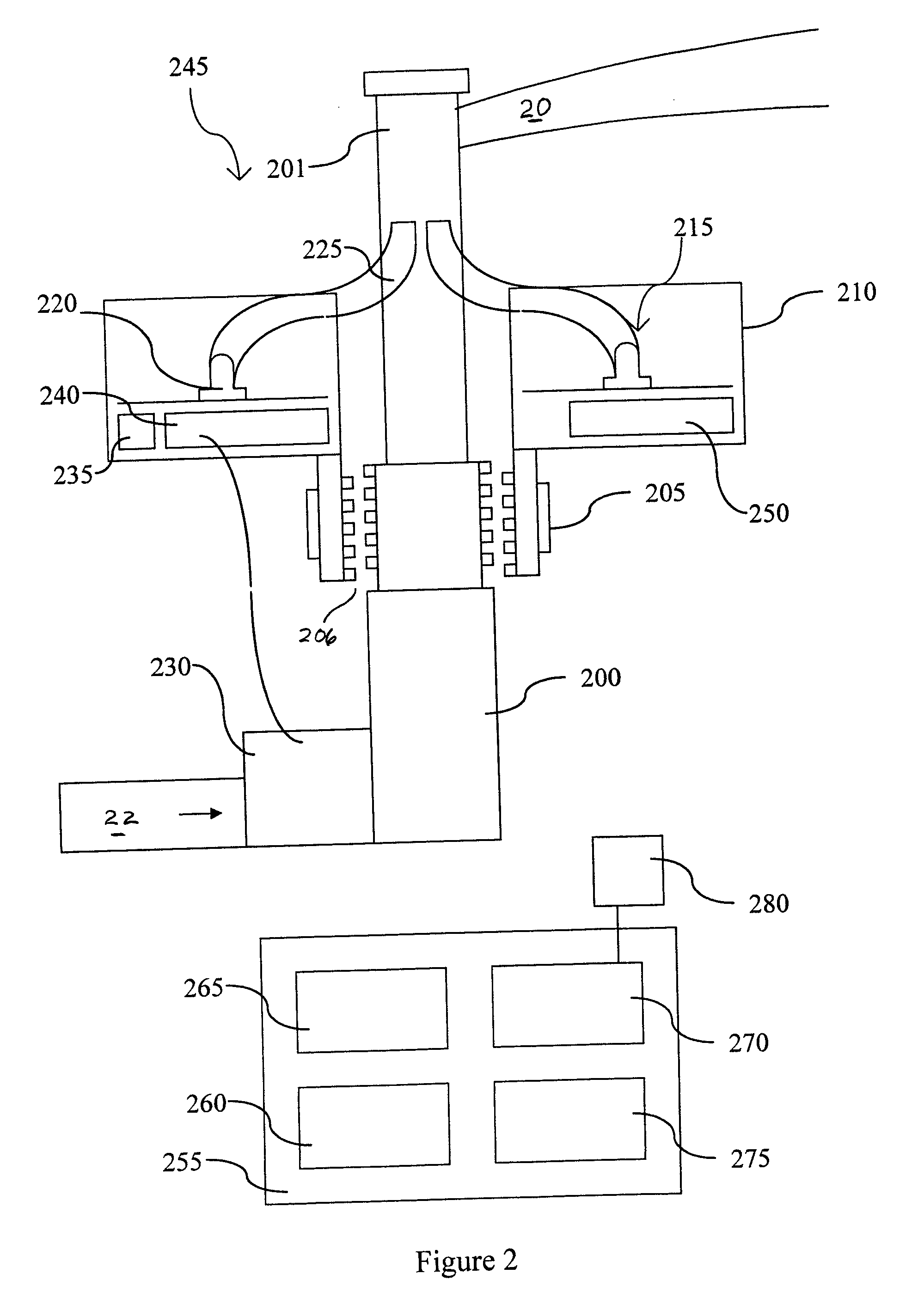
Figure 3
Abstract
Description
FIELD OF THE INVENTION
[0001] This invention relates to a lighting process and mechanism, and, in particular, to the combination of a lighting system with a sprinkler. BACKGROUND OF THE INVENTION
[0002] In cases where it is intended to place a light marking or light a lawn or a piece of land, whether public or private, it is a present imperative to provide, for each marker or lighting source, a rather bulky and expensive mechanical stand. In the absence of such support, the markers or lighting sources would risk being buried in the ground within a few weeks or months. Moreover, the sets including the marker and the stand are not completely watertight and do not provide a guarantee against the formation of vapour in certain cases.BRIEF DESCRIPTION OF THE DRAWINGS
[0003] FIG. 1 is a schematic view showing a first mode of producing the lighting mechanism forming the subject matter of this invention;
[0004] FIG. 2 is a schematic view showing a second mode of producing the lighting mechani...