
Delayed host wakeup for wireless communications device

a wireless communication and host technology, applied in the field of wlan technology, can solve the problem of narrow context of these techniques, and achieve the effect of enhancing power savings in a wlan terminal

Inactive Publication Date: 2007-10-11
NOKIA CORP
View PDF25 Cites 89 Cited by
  • Summary
  • Abstract
  • Description
  • Claims
  • Application Information

AI Technical Summary

Benefits of technology

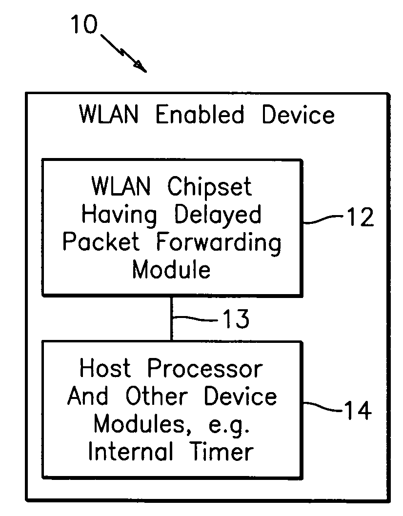
[0018]In effect, the present invention provides a basic technique to reduce power-consumption of an idle WLAN enabled device that is connected to a network by deferring packet delivery and having the knowledge of the host processor state.
[0020]In one embodiment, the present invention provides a method for enhancing power savings in a WLAN terminal, having the following steps: receiving one or more data packets from a wireless communications network; obtaining information regarding operational state of a host processor; and if the host processor is in sleep state, delaying forwarding of the one or more data packets to the host processor until one or more threshold criteria is met.

Problems solved by technology

Currently, when a packet arrives to a WLAN chipset it is passed straight to a host processor and thus possibly waking up the host processor from a deep-sleep.
While filtering of common packets (i.e. ARP request) is done by some known vendors, theses techniques are restricted to a very narrow context (i.e. the ARP packets).

Method used


Image

  • Delayed host wakeup for wireless communications device
  • Delayed host wakeup for wireless communications device
  • Delayed host wakeup for wireless communications device

Examples


example 1

Chipset Time-Out

[0044]Time 0 ms: The WLAN chipset 12 may receive a broadcast packet from the network or other device (not shown), but it also detects that the host processor 14 is in a deep-sleep so it decides not to pass the packet up just yet.

[0045]Time 300 ms: The WLAN chipset receives another broadcast packet, but as the host processor 14 is still in the deep sleep it decides to buffer this packet as well.

[0046]Time 800 ms: The WLAN chipset internal timer 22 has been fired and it decides to wake up the host processor 14 by raising an interrupt pin and thus it gets to deliver the packet to the host processor 14.

example 2

Host Processor Awakens

[0047]Time 0 ms: The WLAN chipset 12 receives a broadcast packet from the network or other device (not shown) but it also detects that the host processor 14 is in a deep-sleep so it decides not to pass the packet up just yet.

[0048]Time 200 ms: The host processor 14 is woken up by some internal timer, such as that shown in FIG. 3.

[0049]Time 200.001 ms: The WLAN chipset 12 has detected that the host processor 14 has woken up (e.g. via the signal exchange along line 13) and it raises a receive (RX) interrupt and thus delivers the packet to the host processor 14.

Implementation of the Functionality of Module 24

[0050]By way of example, and consistent with that described herein, the functionality of the modules 24 may be implemented using hardware, software, firmware, or a combination thereof, although the scope of the invention is not intended to be limited to any particular embodiment thereof. In a typical software implementation, the module 12 and 22 would be one o...


PUM


Abstract

A new and unique method or apparatus for power savings in a node, point, terminal or device in a wireless local area network (WLAN), or other suitable network, featuring one or more steps for delaying forwarding one or more data packets from a WLAN chipset to a host processor based on information received by the WLAN chipset about whether the host processor is in a sleep state. The host processor has a clock request pin to indicate when it is in the sleep state. The WLAN chipset has a pin that is connected to a sleep state signal of the host processor so that the WLAN chipset knows when it can wake up the host processor or not. The WLAN chipset has an internal threshold timer to fulfil latency requirements for delivering packets to the host processor.

Description

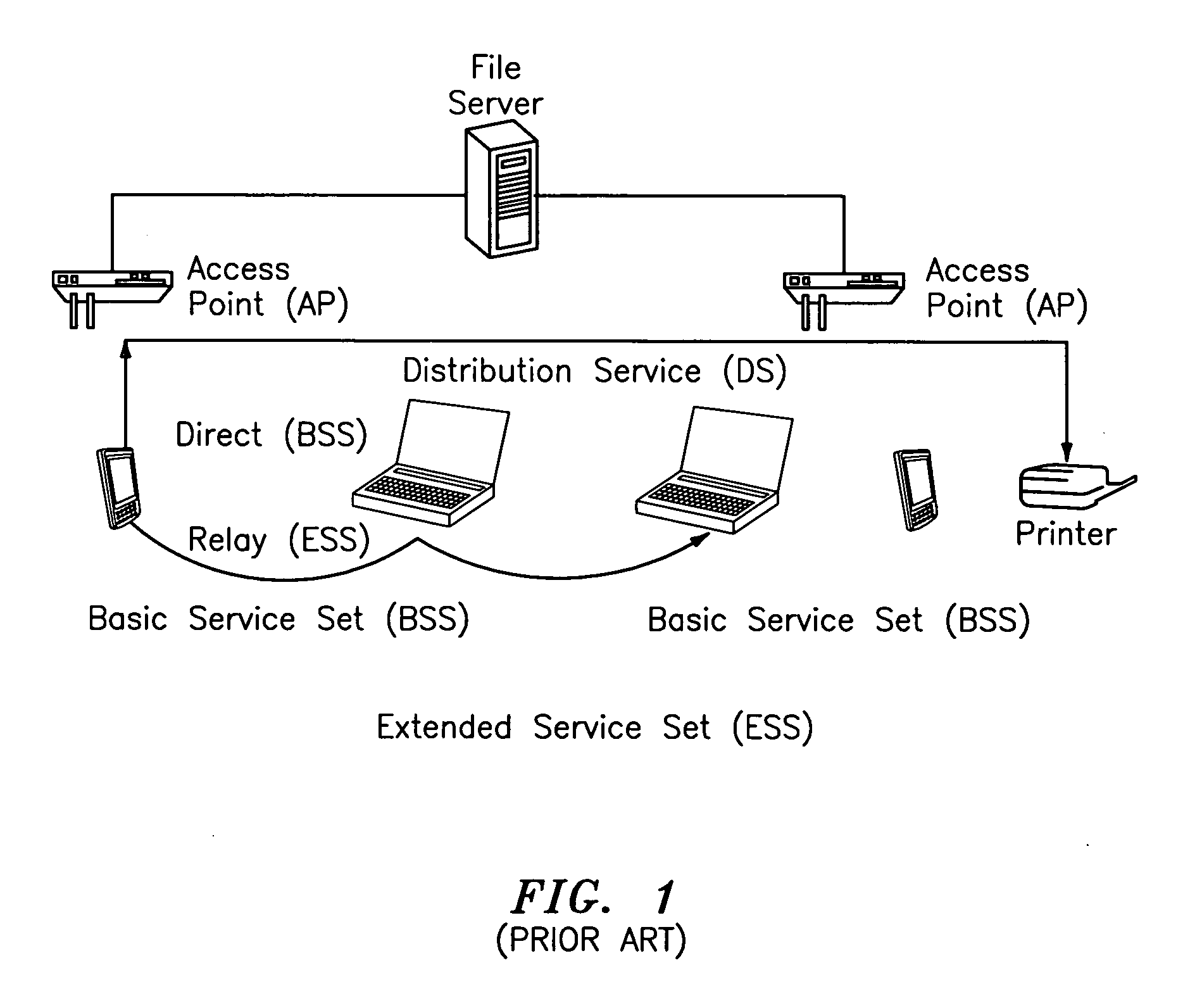
BACKGROUND OF THE INVENTION[0001]1. Field of Invention[0002]The present invention relates to WLAN technology and its system architecture as well as host processor power-management policies in mobile application processors, including that set forth in IEEE 802.11. More particularly, the present invention relates to power savings in the WLAN environment, and providing a method and system for reducing power consumption in WLAN host processor by providing means to synchronizing host wake-up events to host processor power-state by delaying forwarding packets received via a WLAN interface until host processor is in active state or waiting r a certain amount of time to enhance power savings in the host processor.[0003]2. Description of Related Art[0004]FIG. 1 shows, by way of example, typical parts of an IEEE 802.11 WLAN system, which is known in the art and provides for communications between communications equipment such as mobile and secondary devices including personal digital assistan...

Claims


Application Information

Patent Timeline
IPC IPC(8): H04B1/16H04B1/38
CPCH04W52/0251Y02B60/50H04W84/12Y02D30/70H04W72/12H04W52/02
Inventor JAAKKOLA, MIKKO
Owner NOKIA CORP
Learn More