Swing exercise machine

a technology of swinging exercise machine and swinging motion, which is applied in the direction of rocking horse, gymnastic exercise, instruments, etc., can solve the problems of no specific proposal of the direction of the periodic swing motion, and the trainer may stumble along the way of the exercis

Inactive Publication Date: 2007-10-11
MATSUSHITA ELECTRIC WORKS LTD
View PDF45 Cites 13 Cited by
  • Summary
  • Abstract
  • Description
  • Claims
  • Application Information

AI Technical Summary

Benefits of technology

[0008] A purpose of the present invention is to provide a swing exercise apparatus which can switch the driving direction of the periodic swing mo

Problems solved by technology

In addition, parts of the body which can receive stimulation by the simple motion are limited, so that the exercise becomes modestly beneficial.
Furthermore, although the exercise must be continued in a predetermined term to obtain an effect, the trainee will be tired of the exe

Method used


Image

  • Swing exercise machine
  • Swing exercise machine
  • Swing exercise machine

Examples


first embodiment

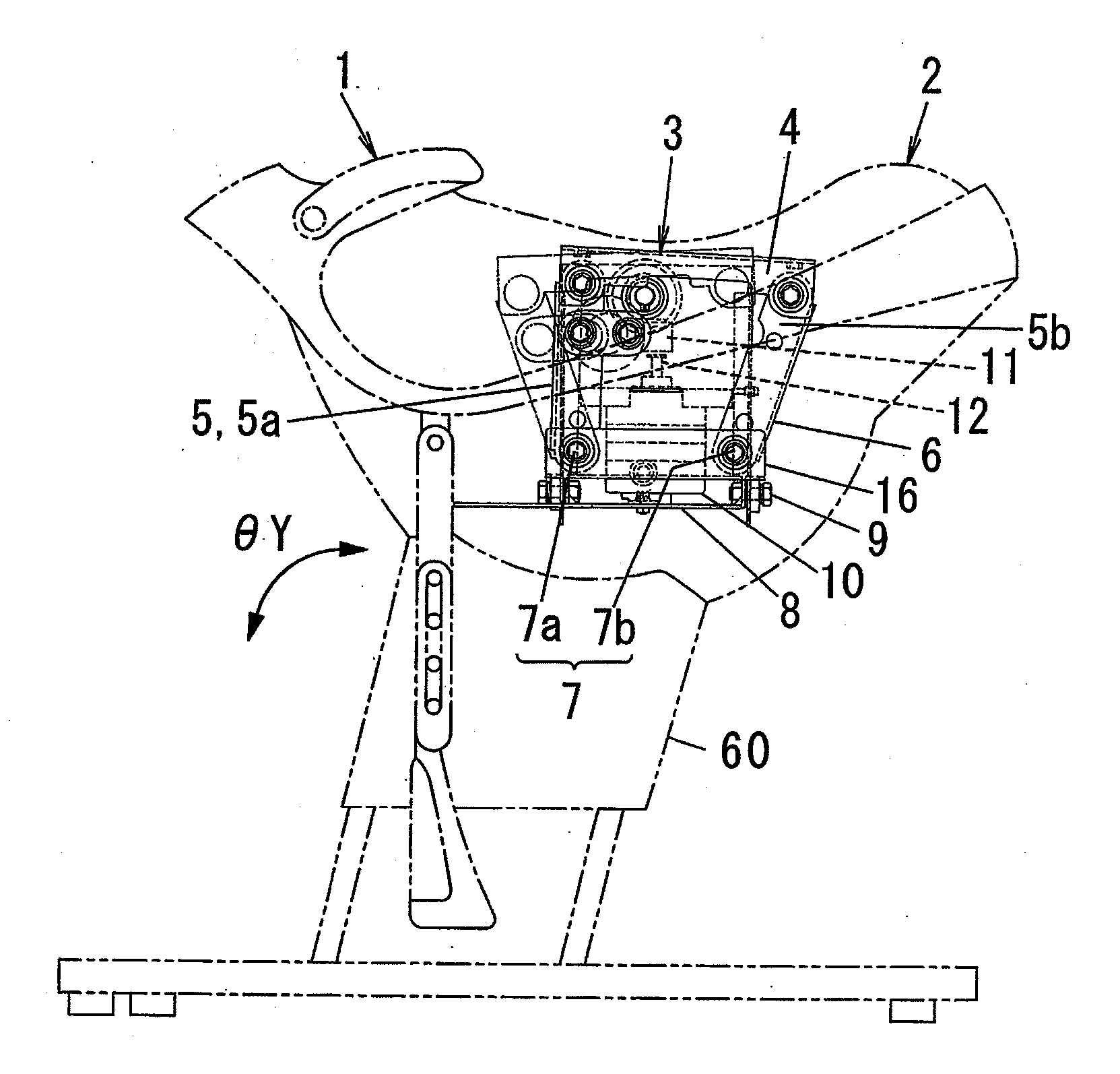
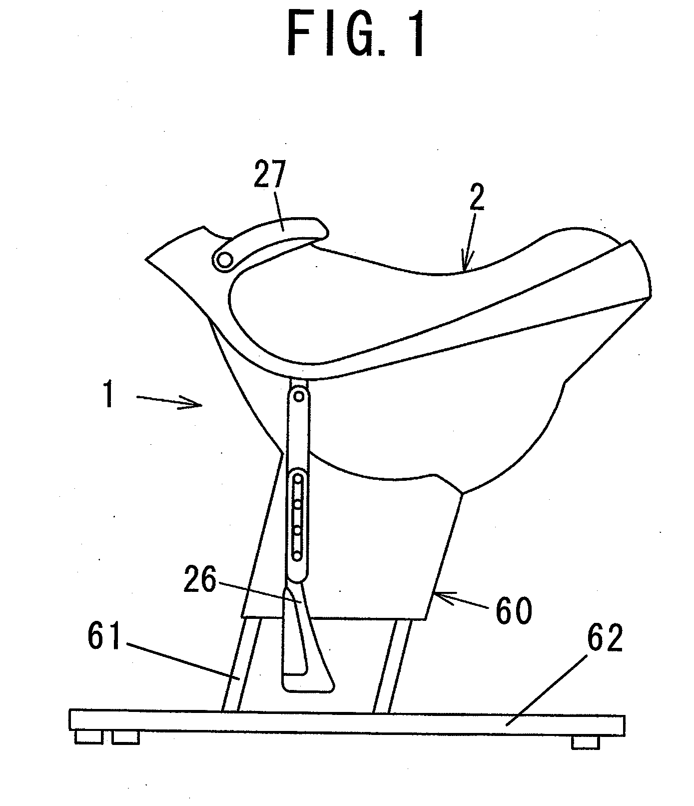
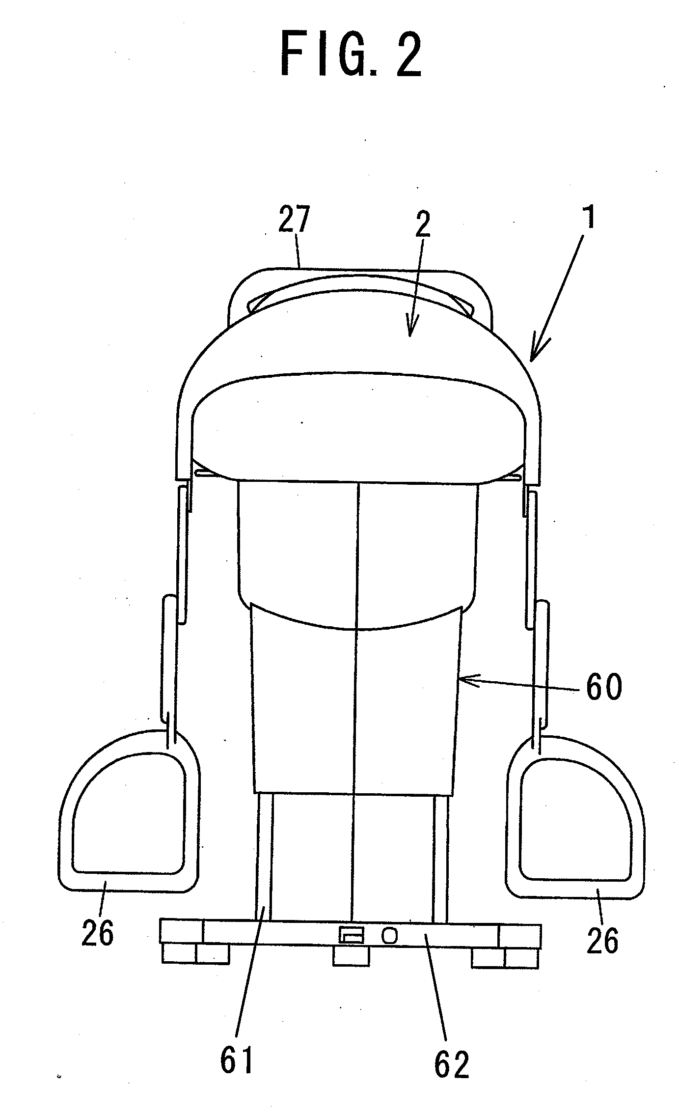
[0042] A swing exercise machine in accordance with a first embodiment of the present invention is described with reference to the figures. FIG. 1 is a side view and FIG. 2 is a rear view respectively showing an appearance of the swing exercise apparatus 1. FIG. 3 is a side view showing a configuration of the swing exercise machine 1. FIG. 4 is a side view showing a detailed configuration of a seat driving apparatus 3 of the swing exercise machine 1. FIGS. 5 and 6 are respectively plain view and rear view of the seat driving apparatus 3.

[0043] The swing exercise machine 1 is comprised of a seat 2 which is similar to a saddle shape or a horseback shape, the seat driving apparatus 3 which is provided in an inside of the seat 2 and periodically swings the seat 2 in at least one direction among X, Y, Z, θX, θY and θZ directions (see FIG. 7B), and a stem 60 which supports the seat 2 and the seat driving apparatus 3. The stem 60 has legs 61 which can be elongated and contracted with respe...

second embodiment

[0057] A swing exercise machine in accordance with a second embodiment of the present invention is described. In the above mentioned first embodiment, the seat driving apparatus 3 of the swing exercise machine 1 needs only one motor 10. A seat driving apparatus 3′ of the swing exercise machine 1 of the second embodiment uses a plurality of, for example, two motors 10a and 10b which individually drives a pedestal 4 around an anteroposterior swing shaft 58 and a transverse swing shaft 59 as shown in FIGS. 9A and 9B.

[0058] In the seat driving apparatus 3′, a movable table 6 and a base plate 8 are rotatably coupled with each other via the anteroposterior swing shaft 58 so as to enable to swing around the anteroposterior swing shaft 58, and thereby, enabling to swing a pedestal 4 or a seat 2 in a direction shown by arrow “θX” with a driving force of the motor 10a, as shown in FIG. 9A. Both ends of the transverse swing shaft 59 are pivoted on a pair of front links 5a. An end of an arm li...


PUM


Abstract

In a swing exercise machine having a seat, a seat driving apparatus that moves the seat along a locus formed by a combination of a periodic swing motion around an anteroposterior swing shaft and a periodic swing motion around a transverse swing shaft, and a control circuit that can control rotation speed and rotation direction of a motor. The control circuit can switch the rotation direction of the motor, so that the seat can be moved in a reverse direction along the locus. Since the human body is asymmetrical in the anteroposterior direction, the regions of the human body where muscle activities occur when the seat is moved in the reverse direction are different from those when the seat is moved in a normal direction. Thereby, it is possible to vary the effect of the swing exercise on the human body.

Description

BACKGROUND OF THE INVENTION [0001] 1. Field of the Invention [0002] The present invention relates to a swing exercise machine which swings a seat to provide an exercise effect to a trainee. [0003] 2. Description of the Related Art [0004] For example, Japanese Patents No. 3394889 and 3394890 respectively disclose conventional swing exercise machines such as a balance exercise machine and a lumbago prevention exercise machine, which realize a series of swing patterns of a seat smoothly while a trainee sits on the swinging seat with using a six-axial parallel driving mechanism. [0005] Japanese Laid-Open Patent Publication No. 2005-245638 discloses a conventional electrically moving seat as an exercise machine which moves a disc shaped seat reciprocally in both of an anteroposterior direction and a transverse direction. [0006] Japanese Laid-Open Patent Publication No. 2001-286578 discloses a conventional balance exercise machine which realizes a pitching motion in an anteroposterior dir...

Claims


Application Information

Patent Timeline
IPC IPC(8): A63B22/00A63B71/00
CPCA63B69/04A63B24/00A63G13/06
Inventor NAKANO, TOSHIO
Owner MATSUSHITA ELECTRIC WORKS LTD
Why Eureka
Try Eureka