Display controller and display device provided therewith

a display controller and display device technology, applied in the field of display controllers and display devices provided therewith, can solve the problems of increasing power consumption, increasing the mounting area of the substrate, and not achieving satisfactory display performance, so as to reduce the mounting area of the memory, improve the display quality, and reduce the storage capacity of the memory.

Inactive Publication Date: 2007-01-16
PANASONIC LIQUID CRYSTAL DISPLAY CO LTD +1
View PDF17 Cites 65 Cited by
  • Summary
  • Abstract
  • Description
  • Claims
  • Application Information

AI Technical Summary

Benefits of technology

[0018]According to the present invention described above, display data of an n-th frame and the (n−1)-th frame are compared, and, based on the comparison result, a driving data signal for displaying the n-th frame is generated. Accordingly, it is possible to obtain better display quality without a sense of after-image in displaying a dynamic image.
[0019]Further, according to the present invention, the display data of N pixels of the (n−1)-th frame are read sequentially from the memory, and each time when display data of N pixels of the (n−1)-th frame are read, display data of N pixels of the n-th frame are sequentially written into the memory area from which the display data of N pixels of the (n−1)-th frame have been read. Accordingly, as the storage capacity of the memory, capacity of two frames is not required, since the capacity of one frame is sufficient. In other words, the storage capacity of the memory can be reduced. Thus, it is possible to suppress increase of the mounting area of the memory, increase of power consumption, and price increase. In particular, when display data are compressed before storing into the memory, the mentioned effects become larger. Further, owing to miniaturization of the memory, the memory, the display data conversion means, and the memory control means can be formed on one circuit chip, and as a result, the display controller becomes smaller and of lower cost, furthermore, while realizing high-speed processing.

Problems solved by technology

This becomes a main cause of a sense of after-image when a dynamic image is displayed, and, in the present state, satisfactory displaying performance has not been obtained yet.
This causes problems such as increase of the mounting area of the substrate, increase of the power consumption, increase of the price, and the like.

Method used


Image

  • Display controller and display device provided therewith
  • Display controller and display device provided therewith
  • Display controller and display device provided therewith

Examples


first embodiment

[0043]First, referring to FIGS. 1–10, 21 and 22, a liquid crystal display device of a first embodiment according to the present invention will be described.

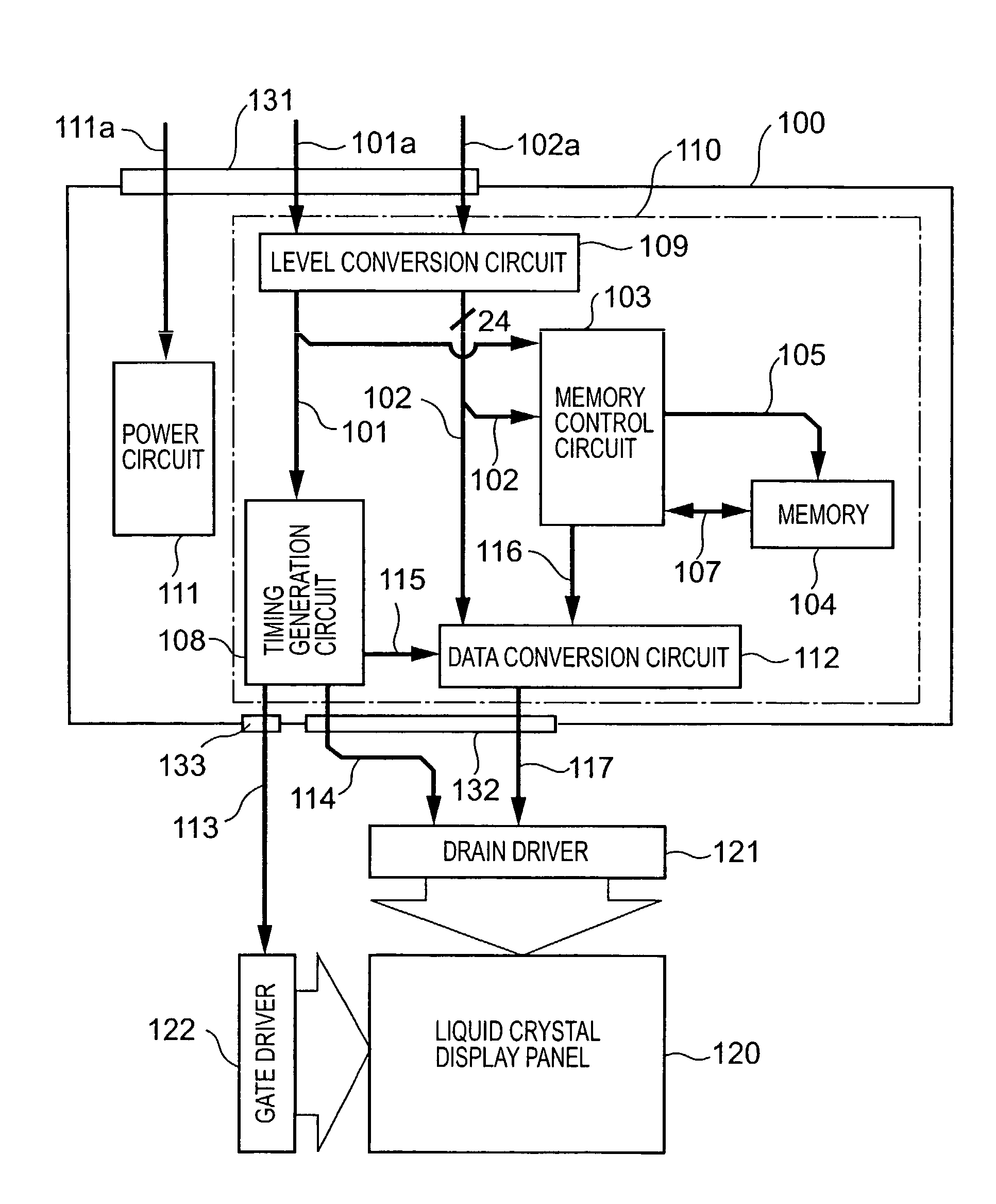
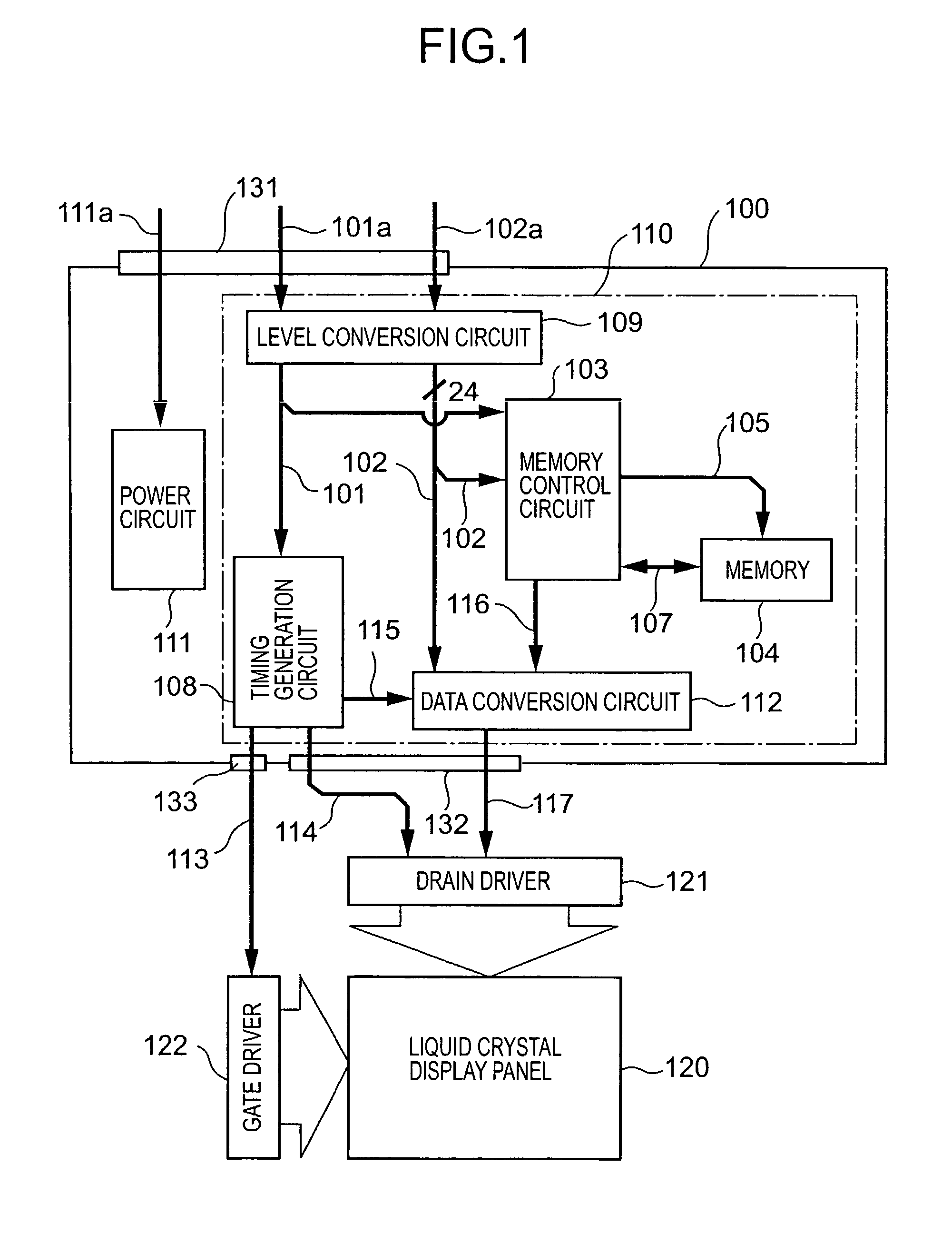
[0044]The liquid crystal display device of the present embodiment comprises a liquid crystal display panel 120, drivers 121 and 122 for driving the liquid crystal display panel 120, and a control circuit 100 for outputting signals to the drivers 121 and 122.

[0045]Although not shown, the liquid crystal display panel 120 is provided with a plurality of drain lines, a plurality of gate lines perpendicular to those drain lines, and pixel electrodes provided correspondingly to intersections of those lines. In the present embodiment, the number of pixels of this liquid crystal display panel 120 is 1024×3×768, and 8 bits of a display signal are inputted to each pixel.

[0046]The drivers 121 and 122 consist of a drain driver 121 for applying voltage on the plurality of drain lines of the liquid crystal display panel 120 and a gate driver 1...

second embodiment

[0086]Next, a liquid crystal display device of a second embodiment according to the present invention will be described referring to FIGS. 11–13.

[0087]The present embodiment is fundamentally similar in its configuration and operation to the first embodiment, except that the phases of the write timing and read timing to the memory 104 are shifted.

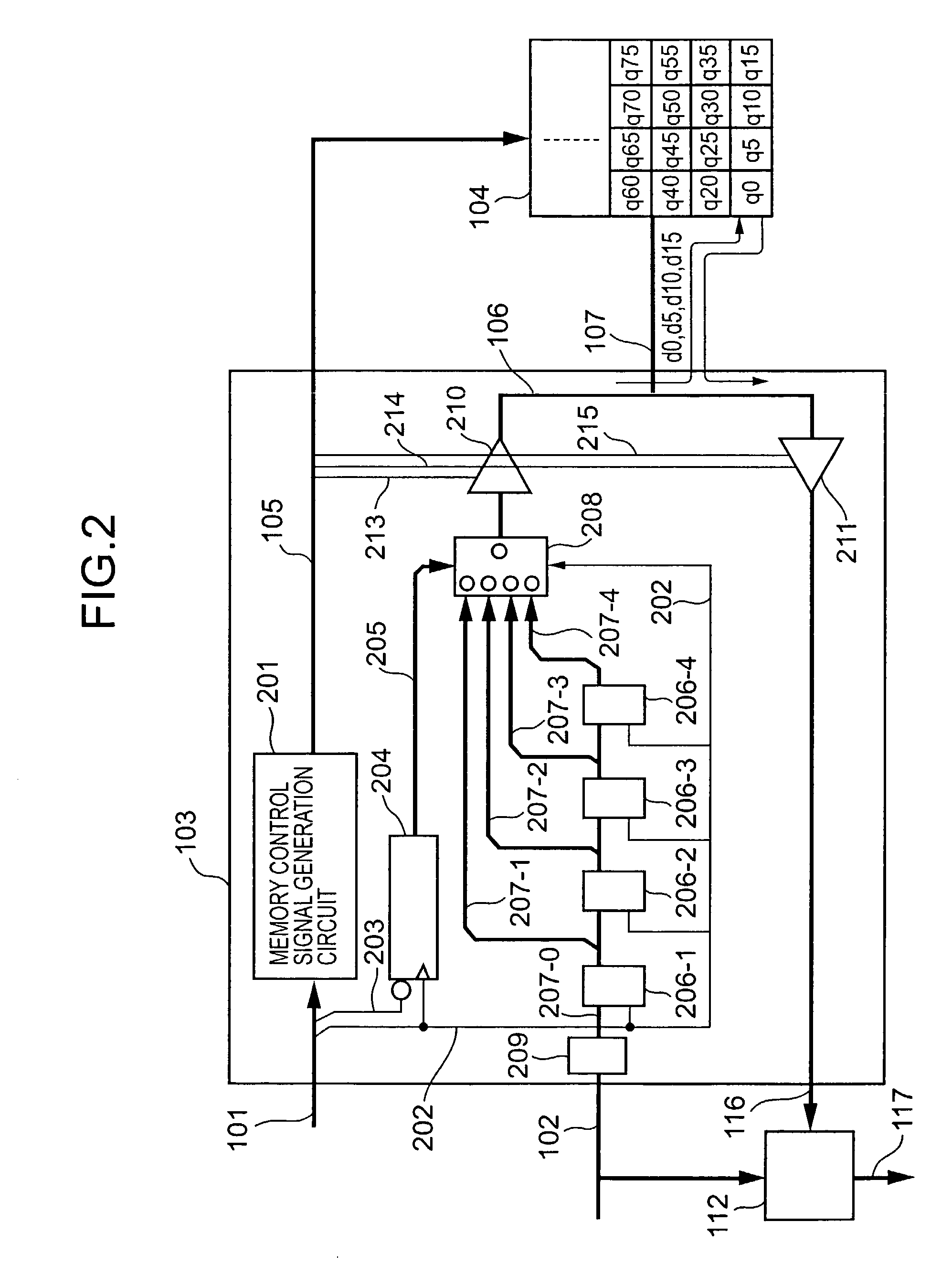
[0088]In the first embodiment, when the inputted display data are q0, q1, q2, q3, q5, q6, . . . , then, on the basis of the data q0 at the display starting point, data of every fifth pixels, q0, q5, q10, . . . are stored into the memory 104. On the other hand, in the present embodiment, on the basis of the data q2 shifted by two pixels from the display starting point, data of every fifth pixels, q2, q7, q12, . . . are stored into the memory 104.

[0089]Further, as shown in FIG. 12, the data of the 0th pixel of the display starting point through the 4th pixel are set to q2, the display data of the 5th pixel through the 9th pixel are set to q7, ...

third embodiment

[0092]Next, a liquid crystal display device of a third embodiment according to the present invention will be described referring to FIGS. 14–16.

[0093]In both the above embodiments, out of inputted display data of 5 pixels, display data of one pixel is stored as a representative value into the memory. When the memory display data is used, all the display data of 5 pixels concerned are considered to have the same value as the representative value stored in the memory. On the other hand, in the present embodiment, an average value of inputted display data of 5 pixels is obtained, and stored as a representative value into the memory. When the memory display data is used, all the inputted display data of 5 pixels concerned are considered to have the same value as the average value, i.e., the representative value stored in the memory.

[0094]Accordingly, the present invention is fundamentally similar to the first embodiment except that the memory control circuit 103a for controlling writing...


PUM

PropertyMeasurementUnit
color driftaaaaaaaaaa
voltageaaaaaaaaaa
depth-aaaaaaaaaa

Abstract

The present invention can realize better display of a dynamic image, and in addition, can make storage capacity of a memory smaller. A data conversion circuit 112 compares display data 102 of an n-th frame from the outside and display data 116 of the (n−1)-th frame stored in the memory 104, to generate a driving data signal 117 to deliver to a driver. Each time when a memory control circuit 103 reads display data q0, q5, q10, q15 corresponding to 20 pixels out of the display data 116 of the (n−1)-th frame, the memory control circuit 103 compresses display data d0–d19 of 20 pixels out of the display data 102 of the n-th frame from the outside to generated d0, d5, d10, d15, and stores the generated data into the same area where the display data q0, q5, q10, q15 of the display data of the (n−1)-th frame have been stored.

Description

BACKGROUND OF THE INVENTION [0001]1. Field of the Invention[0002]The present invention relates to a display controller that outputs a driving signal to a driver circuit of a display part according to display data received from the outside, in particular, a display controller that improves dynamic image displaying performance, and to a display device provided with this display controller.[0003]2. Related Art Statement[0004]In an active matrix liquid crystal display device, display data inputted from an outside system are transformed into gradation voltage, and the gradation voltage is supplied as drain voltage to a liquid crystal panel, realizing gradation displaying. Recently, in the field of such an active matrix liquid crystal display device, a liquid crystal panel is advancing toward a larger screen and higher color purity.[0005]However, a now common TFT liquid crystal material has a response speed of about 20–40 ms. This becomes a main cause of a sense of after-image when a dyna...

Claims


Application Information

Patent Timeline
Patent Type & Authority Patents(United States)
IPC IPC(8): G09G5/00G09G3/36G09G5/10G02F1/133G09F9/00G09G3/20H04N5/66
CPCG09G3/3611G09G2320/0261G09G2360/18G09G2340/16G09G2340/02G09G3/36
Inventor OOISHI, YOSHIHISANITTA, HIROYUKIMAEDA, TAKESHIOHIRA, TOMOHIDE
Owner PANASONIC LIQUID CRYSTAL DISPLAY CO LTD
Why Eureka
Try Eureka