Film and antireflection film having fine irregularities on surface, production method for the same, and optical member using the same

a production method and film technology, applied in the direction of roads, instruments, traffic signals, etc., can solve the problems of insufficient anti-reflection performance of films, limited surface structure and size of alumina single components, and insufficient surface roughness of films, etc., to achieve excellent anti-reflection effect, excellent heat resistance, excellent anti-reflection

Inactive Publication Date: 2005-10-20
PUBLIC UNIVERSITY CORPORATION OSAKA CITY UNIVERSITY +1
View PDF17 Cites 62 Cited by
  • Summary
  • Abstract
  • Description
  • Claims
  • Application Information

AI Technical Summary

Benefits of technology

[0011] The present invention has been made in view of the conventional problems, and an object of the present invention is therefore to provide a film in which a fine irregular structure on a surface can be controlled in a wide range, and a production method for the same. Another object of the present invention is to provide a transparent antireflection film which can be applied to an arbitrary transparent base material and shows an excellent antireflection effect for visible light by reducing reflection at an interface between the base material and the irregularities, and to provide an optical member using the same.
[0024] A film structure of the present invention includes fine irregularities mainly composed of alumina on a surface of a transparent thin film layer containing at least one component selected from the group consisting of zirconia, silica, titania, and zinc oxide. Further, a content of the component of the transparent thin film layer can be controlled. Thus, the transparent thin film layer may have a refractive index between those of the fine irregularities and the base material. The refractive index between the fine irregular structure and the base material may be continuously varied, and reflection at an interface between the fine irregular structure and the base material may be reduced to minimum. Further, the size of the fine irregularities can be controlled in a wide range to effectively reduce reflection at an interface between the film and air. The optical member of the present invention can attain a significant effect exceeding those of the conventional techniques.
[0025] The film and the transparent antireflection film of the present invention each have fine irregularities mainly composed of alumina on a surface of a transparent thin film layer containing at least one component selected from the group consisting of zirconia, silica, titania, and zinc oxide, in which a height of the fine irregularities is 0.005 μm to 5.0 μm, an average surface roughness Ra′ is 5 nm or more, and a surface area ratio Sr is 1.1 or more. In the present invention, at least component selected from the group consisting of alumina, zirconia, silica, titania, and zinc oxide is formed into a composite, to thereby provide a wide range for controlling the fine irregular structure compared with that of an alumina single component thin film having a surface fine irregular structure.
[0026] Further, the optical member of the present invention is produced by providing a transparent antireflection film on a base material. To be specific, the optical member of the present invention is produced by providing a transparent thin film layer containing at least one component selected from the group consisting of zirconia, silica, titania, and zinc oxide between the base material and the fine irregularities. Further, the content of the component in the transparent thin film layer can be controlled. Thus, the transparent thin film layer may have a refractive index between those of the fine irregularities and the base material, and the refractive index between the fine irregular structure and the base material may be continuously varied.
[0027] As described above, the film and the transparent antireflection film of the present invention each show an excellent antireflection effect for visible light of low reflectance over wide spectrum for use on any base material. Further, the film and the transparent antireflection film of the present invention are each entirely composed of inorganic components, and the whole production process may be performed at 100° C. or less. Thus, the film and the transparent antireflection film each have excellent heat resistance and may be applied to a base material having poor heat resistance such as an organic polymer. As described above, the film and the transparent antireflection film of the present invention each show an excellent antireflection effect for visible light and can provide a transparent antireflection film and an optical member of excellent productivity, respectively.

Problems solved by technology

Those techniques have problems in transparency due to light diffraction and scattering caused by a large lateral size-of the fine irregular structure, or a problem of a small antireflection effect due to a longitudinal size thereof being too small, in contrast.
Further, a single film component may cause undesirable reflection at an interface between a film and a base material with poor matching in refractive indexes of the film and the base material, and a large antireflection effect may not be expected for an arbitrary base material.
However, the aforementioned alumina single component film has limitations in the surface structure and the size thereof.
However, an actual maximum surface roughness is about 30 nm, and no film having a surface roughness of 30 nm or more is obtained.
Further, the single film component may cause undesirable reflection at an interface between the film and a base material with poor matching in refractive indexes of the film and the base material, and a larger antireflection effect may not be expected for an arbitrary base material.
The film has problems of insufficient antireflection performance due to a small size of the surface irregular structure.
Further, undesirable reflection may occur at an interface between the film and a base material, and thus antireflection performance may degrade.
As described above, the conventional techniques each hardly provide a sufficient range for controlling the size of irregularities of a film having a fine irregular structure on the surface, and hardly develop sufficient antireflection performance.

Method used


Image

  • Film and antireflection film having fine irregularities on surface, production method for the same, and optical member using the same
  • Film and antireflection film having fine irregularities on surface, production method for the same, and optical member using the same
  • Film and antireflection film having fine irregularities on surface, production method for the same, and optical member using the same

Examples


example 1

[0089] A clear float glass substrate (soda lime silicate-based composition) of a size of 100 mm×100 mm and a thickness of about 2 mm was subjected to ultrasonic cleaning with isopropyl alcohol and was dried, to thereby prepare a glass substrate for coating.

[0090] Aluminum sec-butoxide (Al(O-sec-Bu)3) was dissolved in 2-propanol (IPA), and ethyl acetoacetate (EAcAc) was added thereto as a stabilizer. The mixture was stirred at room temperature for about 3 hours, to thereby prepare an Al2O3 sol solution. A molar ratio of the solution was Al(O-sec-Bu)3:IPA:EAcAc=1:20:1.

[0091] Meanwhile, zirconium isopropoxide (Zr(O-iso-Pr)4) was also dissolved in IPA, and EAcAc was added thereto. The mixture was stirred at room temperature for about 3 hours, to thereby prepare a ZrO2 sol solution. The molar ratio of the solution was Zr(O-iso-Pr)4:IPA:EAcAc=1:20:1.

[0092] The ZrO2 sol solution was added into the Al2O3 sol solution in a weight ratio of Al2O3:ZrO2=0.7:0.3. The mixture was stirred for ab...

example 2

[0100] The Al2O3 sol was prepared in the same manner as that in Example 1.

[0101] Meanwhile, tetraethoxysilane (TEOS), IPA, and 0.01 M (HCl aq.) were mixed, and the whole was stirred at room temperature for about 3 hours, to thereby prepare an SiO2 sol solution. A molar ratio of the solution was TEOS:IPA=1:20. An amount of HCl aq. added was a sum of equal moles of Al(O-sec-Bu)3 and twice moles of TEOS. The SiO2 sol solution was added into the Al2O3 sol solution in a weight ratio of Al2O3:SiO2=0.7:0.3, to thereby prepare an Al2O3—SiO2 sol as an application liquid.

[0102] Next, the same glass substrate subjected to the same cleaning treatment as that of Example 1 was immersed in the application liquid, and then an coating film was formed on the surface of the glass substrate through a dipping method (lifting speed of 3 mm / s, 20° C., 56% R.H.). The resultant was dried and then subjected to heat treatment at 100° C. for 1 hour, to thereby obtain a transparent, amorphous Al2O3 / SiO2-based...

example 3

[0105] The SiO2 sol solution used in Example 2 was added into the Al2O3 sol solution used in Example 1 in a weight ratio of Al2O3:SiO2=0.5:0.5, to thereby prepare an Al2O3—SiO2 sol as an application liquid.

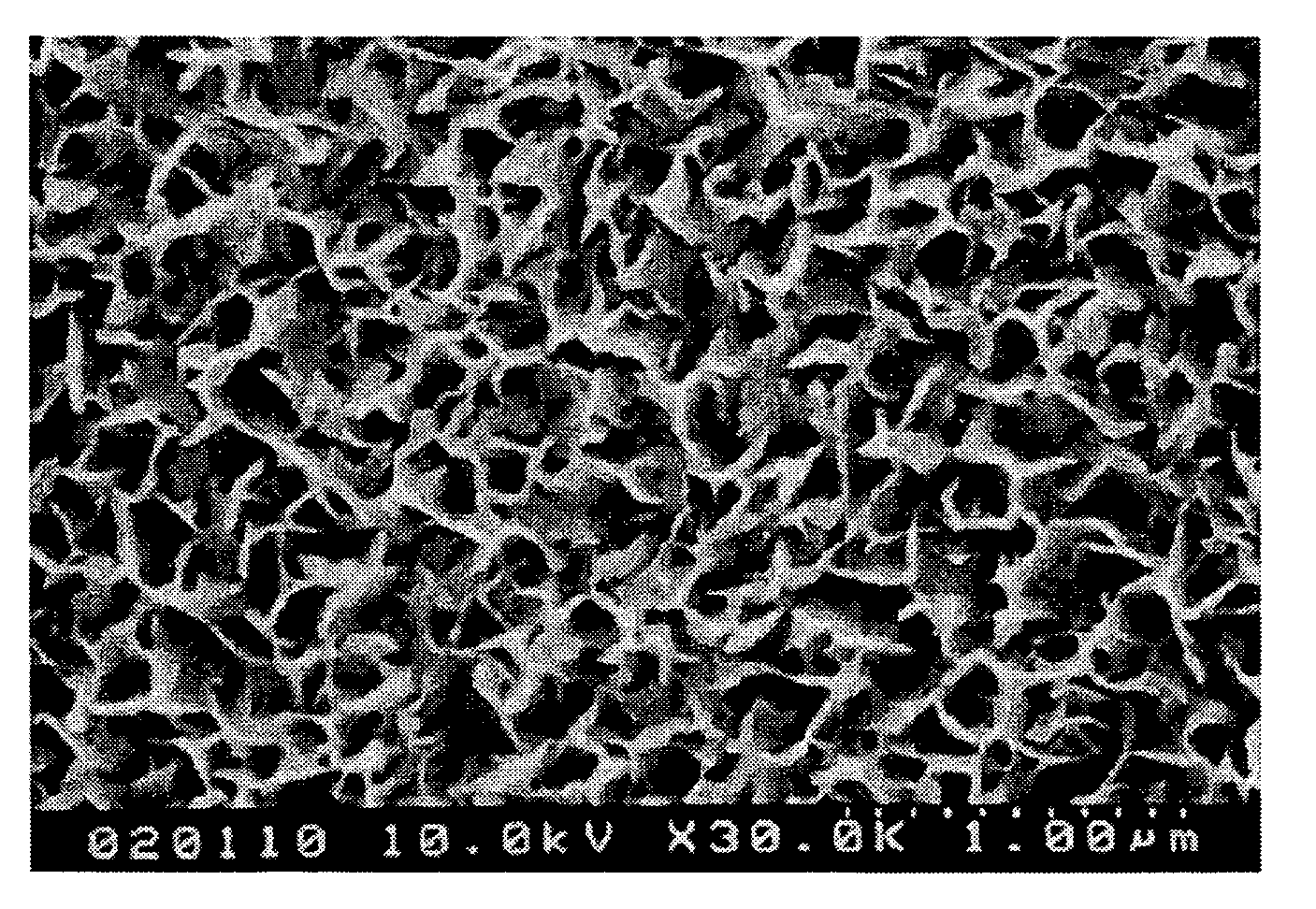
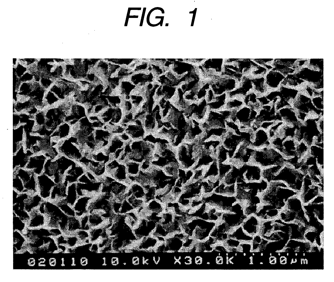
[0106] Next, FE-SEM observation and SPM observation were conducted on the surface of the film formed, subjected to hot water treatment, and dried under the same conditions as those of Example 2, and fine irregularities of plate crystals mainly composed of alumina, similar to those of Example 1, were observed. The average surface roughness Ra′ (nm) and surface area ratio Sr obtained through the SPM measurement were Ra′=75 nm and Sr=2.7, respectively.

[0107] Table 1 shows the relationship between the average surface roughness Ra′ and the film transmittance / reflectance.


PUM

PropertyMeasurementUnit
heightaaaaaaaaaa
roughnessaaaaaaaaaa
weight ratioaaaaaaaaaa

Abstract

A transparent antireflection film, including fine irregularities mainly composed of alumina, and a transparent thin film layer supporting the fine irregularities, in which the transparent thin film layer contains at least one selected from the group consisting of zirconia, silica, titania, and zinc oxide. A production method for the aforementioned transparent antireflection film, including: forming a multicomponent film using an application liquid containing at least one compound selected from the group consisting of a zirconium compound, a silicon compound, a titanium compound, and a zinc compound, and at least an aluminum compound; and subjecting the multicomponent film to warm water treatment.

Description

BACKGROUND OF THE INVENTION [0001] 1. Field of the Invention [0002] The present invention relates to a production method for a film having fine irregularities on a surface, and more specifically to an antireflection film having fine irregularities on a surface and to an optical member using the same. [0003] To be specific, the present invention relates to a film and a transparent antireflection film each having fine irregularities mainly composed of alumina on a surface of a transparent thin film layer containing at least one component selected from the group consisting of zirconia, silica, titania, and zinc oxide. Further, the present invention relates to optical members using the film and the transparent antireflection film including: various displays such as a word processor display, a computer display, a TV display, and a plasma display panel; polarizing plates used for liquid crystal display devices; and sunglass lenses, prescription glass lenses, finder lenses for cameras, pri...

Claims


Application Information

Patent Timeline
Patent Type & Authority Applications(United States)
IPC IPC(8): G02B26/10C03C17/00C03C17/34G02B1/11G02B5/02G03B21/00
CPCC03C1/008C03C17/007C03C17/3417C03C2217/42C03C2217/425C03C2217/475Y10T428/24372C03C2217/73C03C2217/732C03C2217/77G02B1/11Y10T428/24413Y10T428/24355C03C2217/477
Inventor KOTANI, YOSHINORIYAMADA, MASAYUKIZHANG, ZUYIKUBOTA, MAKOTOMINAMI, TSUTOMUTATSUMISAGO, MASAHIROTADANAGA, KIYOHARUMATSUDA, ATSUNORI
Owner PUBLIC UNIVERSITY CORPORATION OSAKA CITY UNIVERSITY
Why Eureka
Try Eureka