Method for producing metal mask for screen printing

a metal mask and screen printing technology, applied in printing, printed circuit manufacturing, manufacturing tools, etc., can solve the problems of plastic deformation of the surface of the product to be treated, sandblasting cuts the metal plate, and increases so as to reduce the cost of production, and reduce the number of production steps

Active Publication Date: 2011-11-01
FUJI MFG CO LTD
View PDF9 Cites 64 Cited by
  • Summary
  • Abstract
  • Description
  • Claims
  • Application Information

AI Technical Summary

Benefits of technology

[0055]With the structure of the above-described present invention, a method for producing a metal mask of the present invention having the following remarkable effects can be obtained.
[0062]Moreover, because the edge portions of the openings are not cut during dross removal, and the subsequent enlargement of these openings is prevented, highly detailed printing can be achieved.

Problems solved by technology

However, as indicated below, there are several disadvantages when removing dross or providing a satin-like finished surface via this type of sandblasting.
However, this type of sandblasting cuts the metal plate, by bombarding abrasive grains ejected at a high speed onto the metal plate forming the metal mask.
As a result, when the surface of the metal plate bombarded has a large amount of force applied thereto via this bombardment, it simultaneously causes plastic deformation of the surface of the product to be treated.
However, when the bending is corrected in this manner, the sandblasting treatment must be consistently conducted on each of the front and back surfaces of the metal plate, so that a total of two sandblasting treatments are required, which thereby increases the cost of production as a result of an increased number of production steps.
In addition, because it is difficult to uniformly apply a compressive force to both surfaces, warpage occurs in the metal plate (metal mask) after the bending is corrected, which in turn reduces the printing quality.
Moreover, when the surface to be treated is a relatively thin metal foil (for example, in the range of 10 μm to 500 μm), the recessed deformations from the sandblasting process become larger, so that processing becomes difficult.
Furthermore, when the metal mask is formed of a plate-shaped metal plate having a relatively thin film thickness, or a metal foil (10 μm to 100 μm), and sandblasting is conducted on this metal plate or foil, the metal substrate bombarded with the abrasive may be damaged by the kinetic energy of the abrasive.
However, when the satin-like finish formed on the surface of the product to be treated after being bombarded with this type of abrasive grain is microscopically observed, countless sharply shaped irregularities are formed in response to the shape of these abrasive grains.
Once the solder paste or the ink paste intrudes into the irregularities formed in the surface of a metal mask sandblasted in this manner, since it cannot be removed, the solder paste or ink paste remains within the irregularities, causing degradation, a change in properties, or hardening thereof etc.
In addition, when the solder paste or ink paste with such a degradation, a change in properties, or hardening thereof, etc., is stripped from the inside of the irregularities by repeatedly employing a metal mask, it is incorporated into the newly supplied solder paste or ink paste and is applied to the product to be treated, so that the printing quality thereof is decreased.
The abrasive grains embedded in the surface of the metal mask in this manner cause the solder paste or ink paste in the portions where these abrasive grains are embedded to be repelled, etc., due to differences in the wettability of the solder paste or ink paste and that of the metal material constituting the metal mask, so that a uniform amount of solder paste or ink paste cannot be supplied or applied.
As a result, the printing quality thereof is inferior, so that detailed printing, etc. cannot be performed.
Accordingly, the actually printing size with respect to a pre-configured printing design is enlarged, so that the printing quality is inferior.
Moreover, the improvements in the printing quality achieved from forming a satin-like finish cannot be obtained in the metal mask produced by the method described in Japanese Patent No. 3160084.

Method used


Image

  • Method for producing metal mask for screen printing
  • Method for producing metal mask for screen printing
  • Method for producing metal mask for screen printing

Examples


example

[0209]In the printing employing the metal mask produced by the method of the present invention (Example), the rolling of the ink paste was achieved, and the painting ink was pushed out of the openings of the mask, so that the image printed on the substrate was identical to the shapes of the openings, etc.

[0210]It was confirmed that in order to roll the solder paste or ink paste, along with the paste properties, such as the surface tension, or viscosity, etc., a printing squeegee drift speed and metal mask surface roughness corresponding thereto also are required, that significant surface roughness, such as that formed by sandblasting, is not really necessary, and that favorable rolling could be accomplished even with the comparatively smooth surface roughness (Ra) of 0.058 μm, as provided in the metal mask of the Example.

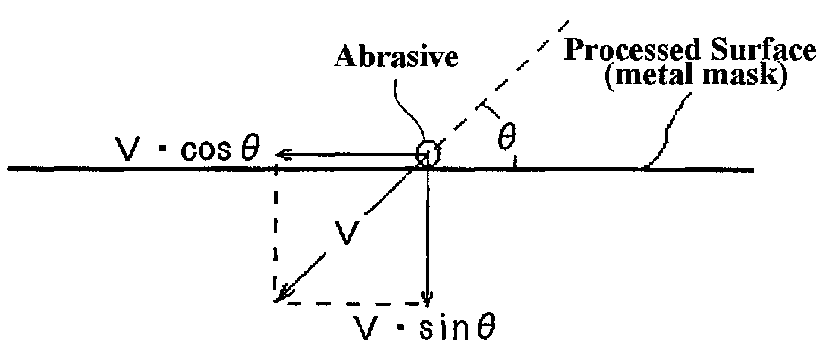
[0211]Moreover, in the metal mask produced by the method of the present invention, because the above-described plate-shaped abrasive or elastic abrasive slides alon...


PUM

PropertyMeasurementUnit
thicknessaaaaaaaaaa
ejection pressureaaaaaaaaaa
incident angleaaaaaaaaaa

Abstract

A method for producing a metal mask for screen printing is provided, in which dross that is deposited at the time a boring operation is conducted via a laser beam is removed, without causing warpage or bending. The method for producing a metal mask for screen printing includes steps of: forming openings in the metal plate by melting the metal plate at positions irradiated by the laser beam; and ejecting an abrasive onto the other surface of the metal plate after the openings are formed. The abrasive ejected in the abrasive ejection step is one having a predetermined flat shape (plate-shaped abrasive), so as to form a plate shape having a flat surface, or an elastically deformable abrasive, with an average grain diameter of a dispersed or carried abrasive grain being 1 mm to 0.1 μm, and which is ejected at an incident angle of equal to or less than 80 degrees with respect to the other surface of the metal plate, and at an ejection pressure of 0.01 MPa to 0.7 MPa or at an ejection speed of 5 m / sec to 150 m / sec, so as to slide along the other surface of the metal plate.

Description

BACKGROUND OF THE INVENTION[0001]1. Field of the Invention[0002]The present invention relates to a method for producing a metal mask for screen printing. More specifically, the present invention relates to a method for producing a metal mask for screen printing that includes steps of: forming opening portions for printing (hereinafter referred to as “opening”) via laser irradiation, and removing dross (burrs) deposited by the opening forming process.[0003]2. Description of the Related Art[0004]A “metal mask” formed with a pattern of openings that corresponds to the printing pattern on a metal plate such as stainless steel is employed in fields that require relatively detailed printing, such as solder paste printing or photoresist layering during a method for producing printed circuits, IC substrates, etc. Accordingly, when such a metal mask abuts the surface of the product to be treated, and a solder paste or ink paste is applied from the opposing surface with a squeegee, etc., prin...

Claims


Application Information

Patent Timeline
Patent Type & Authority Patents(United States)
IPC IPC(8): B23K26/16B24C1/00B24C11/00B24C1/06B41C1/14
CPCB24C11/005H05K3/1225B41C1/145H05K2203/107
Inventor MASE, KEIJIISHIBASHI, SHOZO
Owner FUJI MFG CO LTD
Why Eureka
Try Eureka