Water-based wind-driven power generation using a submerged platform

a technology of wind-driven power generation and submerged platform, which is applied in the direction of groynes, special-purpose vessels, vessel construction, etc., can solve the problems of low wind-powered energy generation efficiency, low cost of wind-powered energy generation, and limited location

Inactive Publication Date: 2007-07-10
DEMPSTER HARRY EDWARD
View PDF48 Cites 65 Cited by
  • Summary
  • Abstract
  • Description
  • Claims
  • Application Information

AI Technical Summary

Benefits of technology

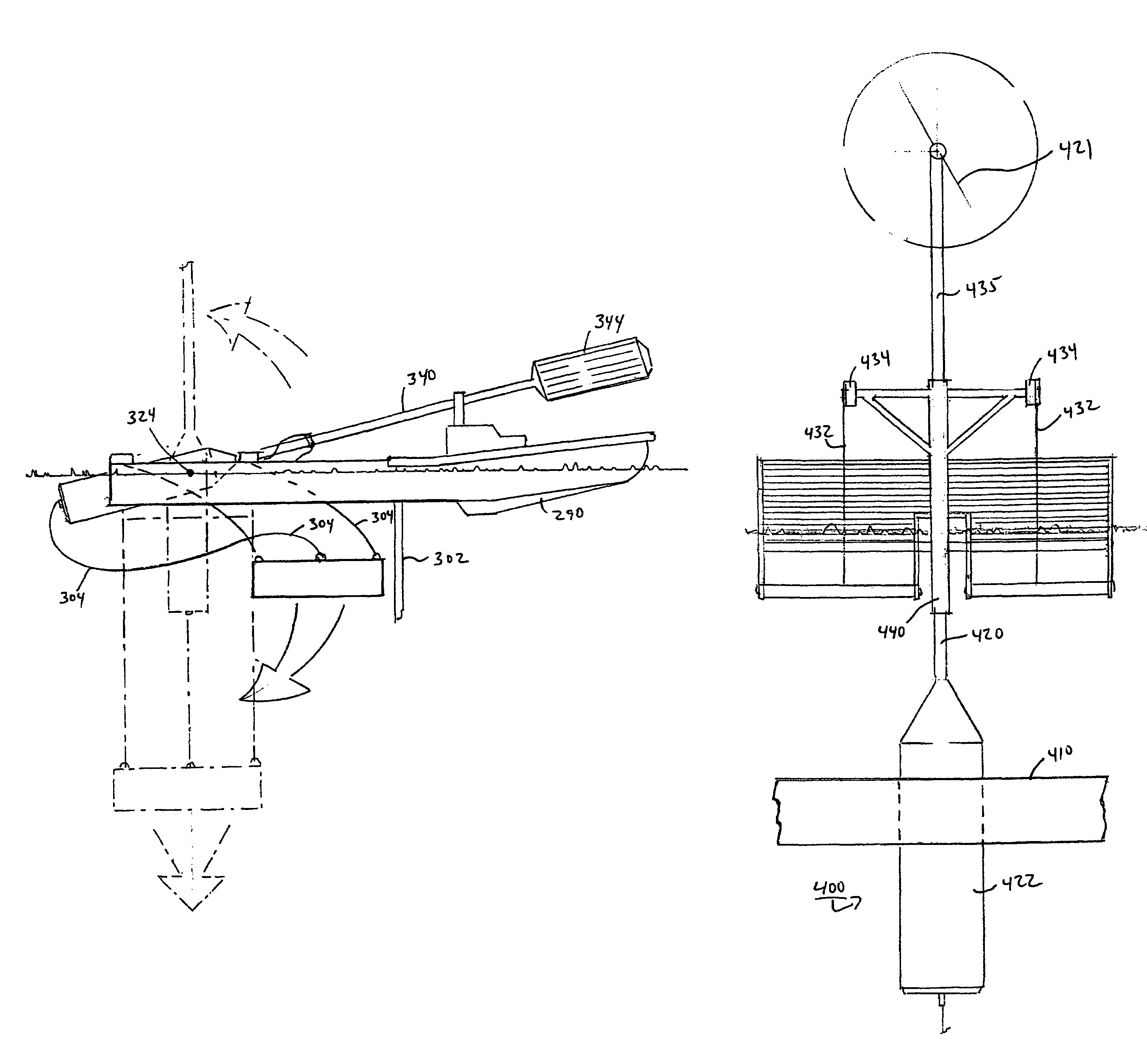
[0010]The present invention addresses this problem by providing systems, methods and techniques by which a wind-powered energy generating platform, secured to an anchor, can pull (or winch) itself beneath the surface of the water and thereby avoid most of the significant effects of storms and waves.
[0012]By virtue of the foregoing arrangement, it often is possible to provide a relatively low-cost apparatus for generating usable energy from wind power. In addition, because the foregoing configuration permits sensitive equipment to be located beneath the surface of the water, such equipment generally can be protected from the most severe ocean currents and turbulence conditions.
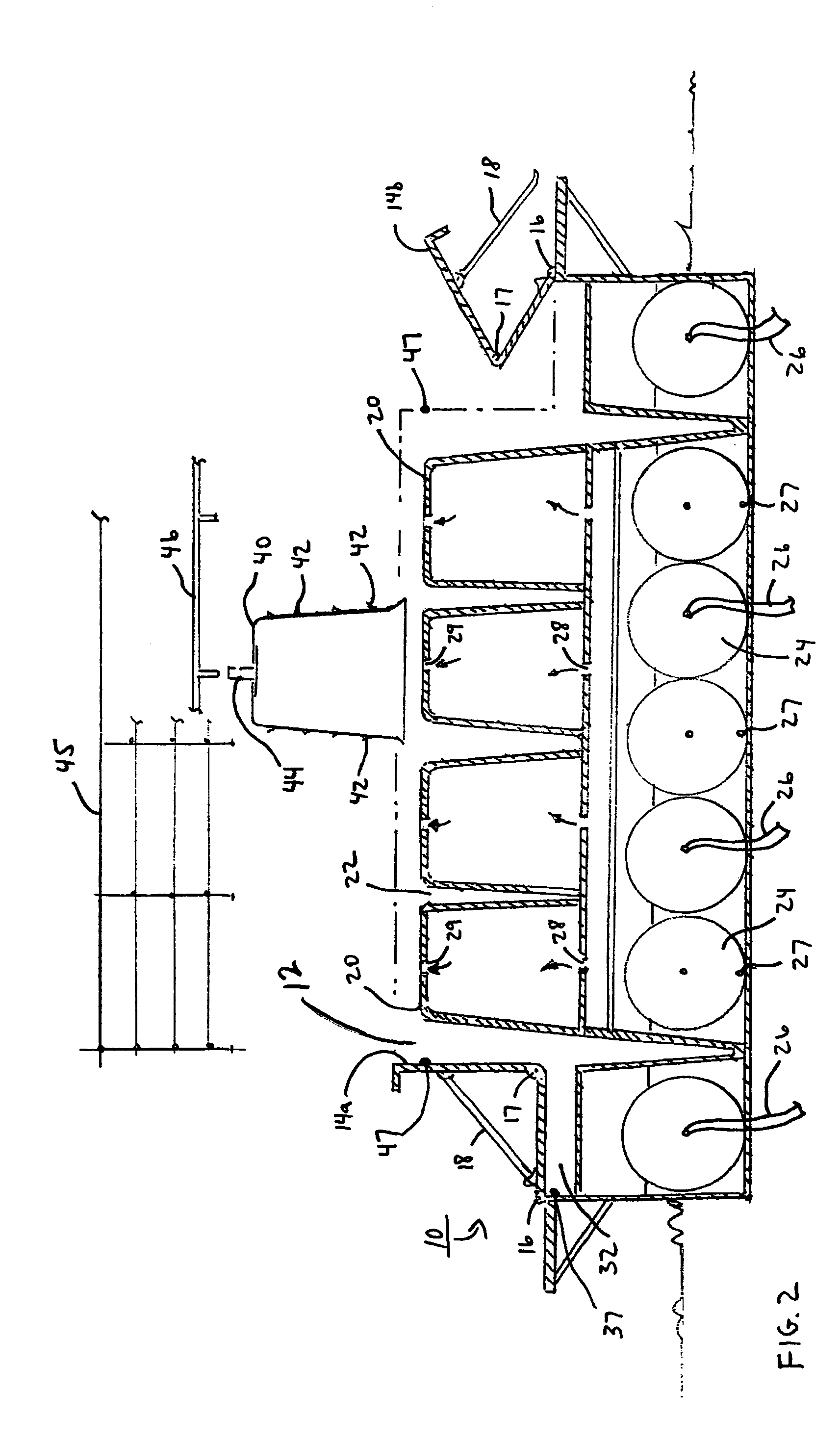
[0014]In another particularized aspect, the anchor includes a plurality of open-bottomed cavities for controlling its buoyancy. And as a result, the anchor can be fabricated, if desired, using the techniques described herein, thereby further reducing costs of production and transportation.

Problems solved by technology

A fairly significant amount of effort has been directed toward generating usable energy from wind power.
However, the costs of wind-powered energy generation often are significantly higher than the costs of alternative energy sources.
However, very few such locations are available, particularly near the locations where power is needed most (e.g., in large cities or near certain manufacturing facilities).
Moreover, where such potential windmill farm sites are available, it may be difficult or costly to obtain the necessary use permits that would enable one to construct a windmill farm.
However, these same conditions also give rise to more severe storms than generally are encountered on land.
Such weather conditions and the potential for large and severe wave conditions make it difficult to construct a power generation facility that can avoid significant damage or destruction and thereby operate over the long term.

Method used


Image

  • Water-based wind-driven power generation using a submerged platform
  • Water-based wind-driven power generation using a submerged platform
  • Water-based wind-driven power generation using a submerged platform

Examples


Embodiment Construction

)

[0042]The first section of the following disclosure describes a system and an apparatus for fabricating a variable-buoyancy structure, as well as discussing the configuration of the final structure itself. Subsequent sections describe various applications in which such a variable-buoyancy structure may be utilized.

Fabricating Technique and Platform.

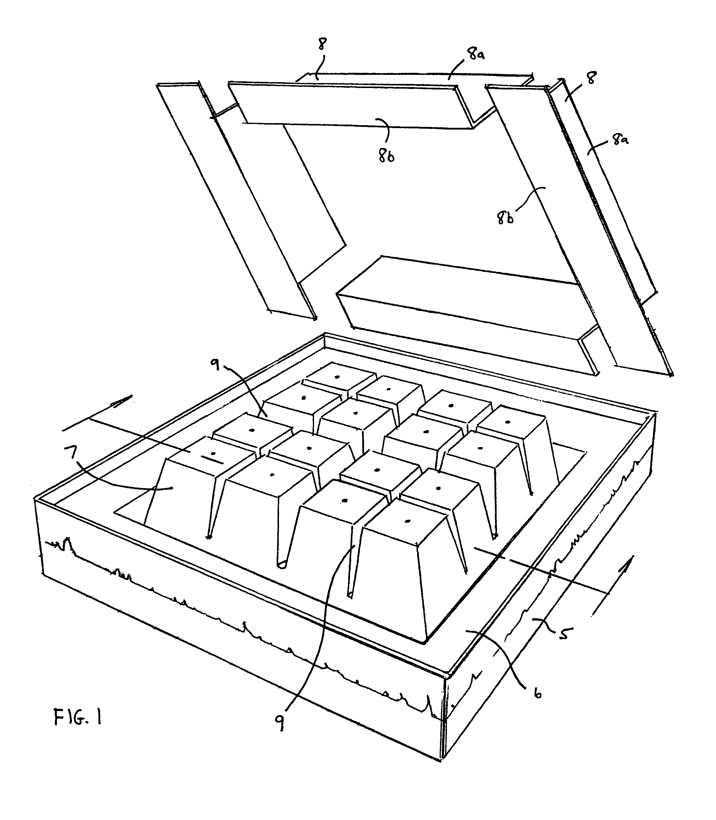
[0043]FIG. 1 is a perspective view of a floating platform 5, having a top surface 6 upon which a mold can be formed for constructing an anchor or other variable-buoyancy structure according to the present invention. Preferably, platform 5 itself has variable buoyancy, allowing it to be submerged and then re-floated. This variable buoyancy may be achieved by installing an array of ballast tanks (e.g., bolted to a series of trusses) underneath surface 6, e.g., in a manner similar to how a conventional dry dock is constructed.

[0044]As shown in FIG. 1, platform 5 has a generally flat top surface 6 upon which an array of forming cells 7 are a...


PUM


Abstract

Provided are systems, methods and techniques by which a wind-powered energy generating platform, secured to an anchor, can pull (or winch) itself beneath the surface of the water and thereby avoid most of the significant effects of storms and waves. In more particularized aspects, a variable-buoyancy anchor is utilized, thereby facilitating the construction and transportation of the entire assembly.

Description

[0001]Priority is claimed to U.S. Provisional Patent Application Ser. No. 60 / 454,665, filed on Mar. 17, 2003, and titled “Ocean Wave / Wind Driven Electrical Generating System”, which application is incorporated by reference herein as though set forth herein in full.BACKGROUND OF THE INVENTION[0002]1. Field of the Invention[0003]The present invention pertains to wind-driven power generation (e.g., electrical power generation) in a water-based environment, and is particularly applicable to the placement of windmills on oceans and other deep bodies of water. The term “windmill” is used herein to mean any apparatus that converts wind energy to useful mechanical energy (typically, rotational mechanical energy).[0004]2. Description of the Related Art[0005]A fairly significant amount of effort has been directed toward generating usable energy from wind power. The advantages of wind power over competing potential energy sources are clear, i.e., wind power is a clean and renewable energy sour...

Claims


Application Information

Patent Timeline
Patent Type & Authority Patents(United States)
IPC IPC(8): F03D9/00F03B13/00F03B13/10F03B13/12H02P9/04B63B21/22B63B21/26B63B21/50B63B35/00B63B35/44E02B3/06F03B13/18F03D11/04
CPCB63B21/22B63B21/26B63B35/00B63B35/44E02B3/062F03B13/1815F03D11/04F03D11/045B63B21/502B63B2035/442B63B2035/446B63B2035/4466B63B2231/60F05B2240/93F05B2240/95F05B2240/97Y02E10/38Y02E10/727F03D13/22F03D13/25Y02E10/30Y02E10/72Y02A10/11
Inventor DEMPSTER, HARRY EDWARD
Owner DEMPSTER HARRY EDWARD
Why Eureka
Try Eureka