Surgical instrument coupling mechanism

a surgical instrument and coupling mechanism technology, applied in the field of surgical instrument coupling mechanism, can solve the problems of inability to fully cooperate with surgeons, inability to use manipulators, and inability to achieve precise surgery,

Active Publication Date: 2007-10-11
AURIS HEALTH INC
View PDF99 Cites 76 Cited by
  • Summary
  • Abstract
  • Description
  • Claims
  • Application Information

AI Technical Summary

Benefits of technology

[0005] In accordance with a first aspect of the present invention, a medical system is provided. The medical system comprises a surgical instrument that carries a distal tool configured for performing a medical procedure on a patient. The medical system further comprises a drive unit (e.g., one having a motor array) configured for controlling the movement of the surgical instrument within at least one degree-of-freedom (e.g., an actuation of the distal tool), and a coupling mechanism through which the surgical instrument is operably coupled to the drive unit. The coupling mechanism may be, e.g., a guide tube through which the surgical instrument is disposed. The medical system further comprises an integrated drape assembly having a drape insert through which the coupling mechanism is coupled to the surgical instrument, and a sterile drape covering the coupling mechanism. In one embodiment, the drape insert is composed of a stiff material.

Problems solved by technology

Although current laparoscopy limits dexterity, and robotics restores dexterity, presently, existing systems, using manipulators both with and without haptic feedback, are generally too bulky and heavy for many minimally invasive procedures, or are too weak and imprecise for surgery.

Method used


Image

  • Surgical instrument coupling mechanism
  • Surgical instrument coupling mechanism
  • Surgical instrument coupling mechanism

Examples


Embodiment Construction

[0033] A description of preferred embodiments of the invention follows.

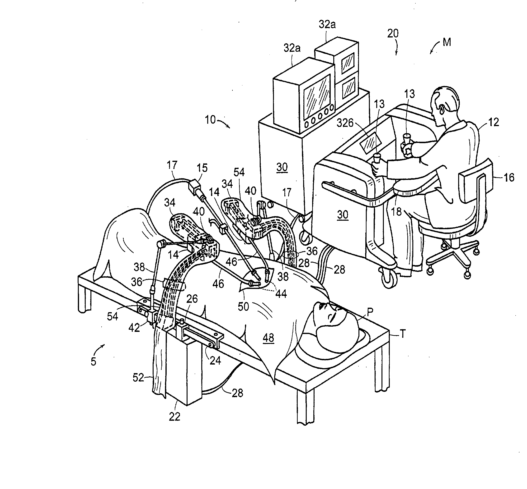
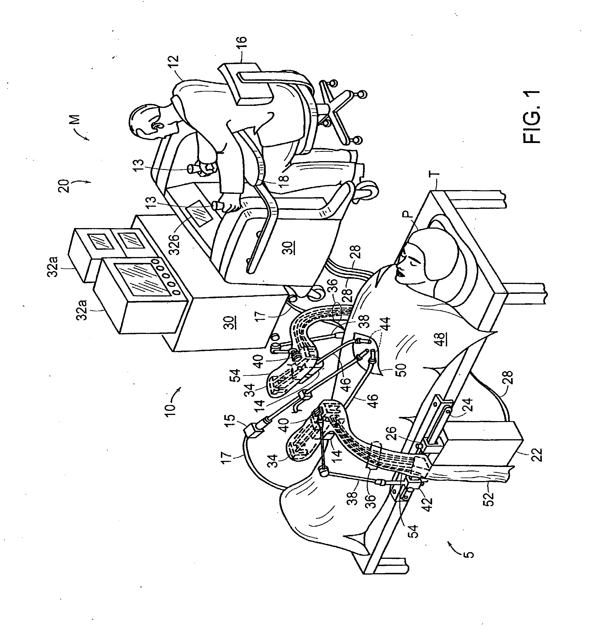
[0034] The surgical robotic system of the present invention, illustrated generally at 10 in FIG. 1, although preferably used to perform minimally invasive surgery, can also be used to perform other procedures as well, such as open or endoscopic surgical procedures. Certain details of the operation of the system 10 are described in U.S. application Ser. No. 10 / 014,143 filed Nov. 16, 2001, by Brock and Lee, the entire contents of which are incorporated herein by reference.

[0035] The surgical instrument system 10 includes two main components, a master station M and a slave station S. At the master station M, a surgeon 12 manipulates an input device 13 to direct the operation of a surgical instrument 14 of the slave station S to perform a medical procedure on a patient P lying on an operating table T. Although there are shown two surgical instruments 14 positioned on either side of an endoscope 15 and controlled by...


PUM


Abstract

A medical system and an integrated drape assembly for a medical system is provided. The medical system comprises a surgical instrument that carries a distal tool configured for performing a medical procedure on a patient, a drive unit configured for controlling the movement of the surgical instrument within at least one degree-of-freedom, a coupling mechanism through which the surgical instrument is operably coupled to the drive unit, and an integrated drape assembly having a drape insert through which the coupling mechanism is coupled to the surgical instrument, a sterile drape covering the coupling mechanism. The drape assembly may comprise a coupling element mounted within the drape insert. The coupling element may be configured for coupling a driver element of the medical system to a driven element of the medical system.

Description

RELATED APPLICATIONS [0001] This application is a continuation of U.S. application Ser. No. 10 / 302,804, filed Nov. 21, 2002, which claims benefit of priority from U.S. application Ser. No. 60 / 409,530, filed Sep. 9, 2002. This application is also related to application Ser. No. xx / xxx,xxx (Attorney Docket No. HNMD-EA007 CON2), filed on the same date herewith. The disclosures of these applications are expressly incorporated herein by reference.BACKGROUND OF THE INVENTION [0002] For certain medical procedures, minimally invasive surgery has replaced conventional surgery where the patient's body cavity is open to permit the surgeon's hands and instruments access to the cavity and internal organs. Minimally invasive procedures are typically less traumatic than conventional surgery, in part, because of the significant reduced incision size through which the medical instruments are inserted. [0003] A video camera may be inserted into the patient in the area of the surgical site to view the...

Claims


Application Information

Patent Timeline
Patent Type & Authority Applications(United States)
IPC IPC(8): A61B19/00A61B17/00
CPCA61B19/081A61B19/2203A61B19/5212A61B2019/2246A61B2019/2223A61B2019/2242A61B2017/00477A61B34/30A61B34/37A61B34/71A61B46/10A61B90/361A61B2034/715
Inventor LEE, WOOJINMAZZUCA, MICHAEL J.GORHAN, MICHAEL C.
Owner AURIS HEALTH INC
Why Eureka
Try Eureka