Press working method and press working apparatus

a press and working method technology, applied in the direction of metal-working apparatus, manufacturing tools, shaping tools, etc., can solve the problems of increasing work time and work cost, difficult to temporarily stop the die, and difficult to change the speed of the die according to a working condition, so as to achieve effective press working and shorten the working time

Inactive Publication Date: 2007-10-18
HONDA MOTOR CO LTD
View PDF5 Cites 20 Cited by
  • Summary
  • Abstract
  • Description
  • Claims
  • Application Information

AI Technical Summary

Benefits of technology

[0015]One or more embodiments of the present invention provide a press working method and a press working apparatus capable of effectively conducting press working on a plate a plurality of times in a short period of working time.

Problems solved by technology

In this type mechanical press, since a die is continuously moved upward and downward, it is difficult to change a speed of the die according to a working condition.
Further, it is also difficult to temporarily stop the die.
With respect to the other working which can not be executed only by the upper die, it is necessary to provide another independent working means, which can be a factor to increase the working time and working cost.
Further, it takes labor to convey a plate between the apparatus.
In this connection, when the plate is held by the holder at the time of press working, depending upon a shape of a product to be formed, an excessively high tension is given to the plate concerned.
Further, excessively small wall thickness portions may be generated on the product to be formed.
Therefore, it is impossible to effectively apply the method described in Patent Document 3 to forming of mass-produced products.

Method used


Image

  • Press working method and press working apparatus
  • Press working method and press working apparatus
  • Press working method and press working apparatus

Examples


first exemplary embodiment

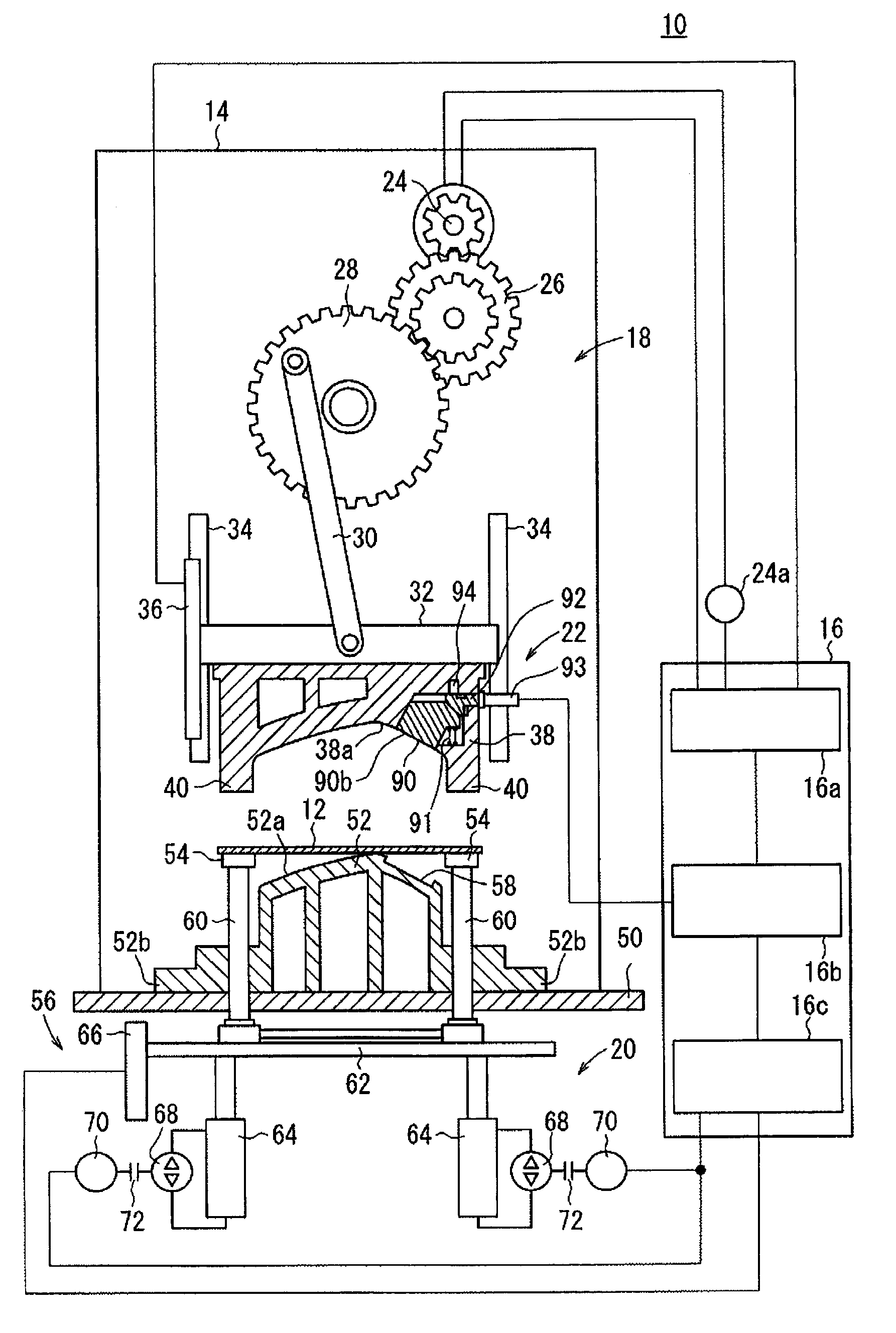
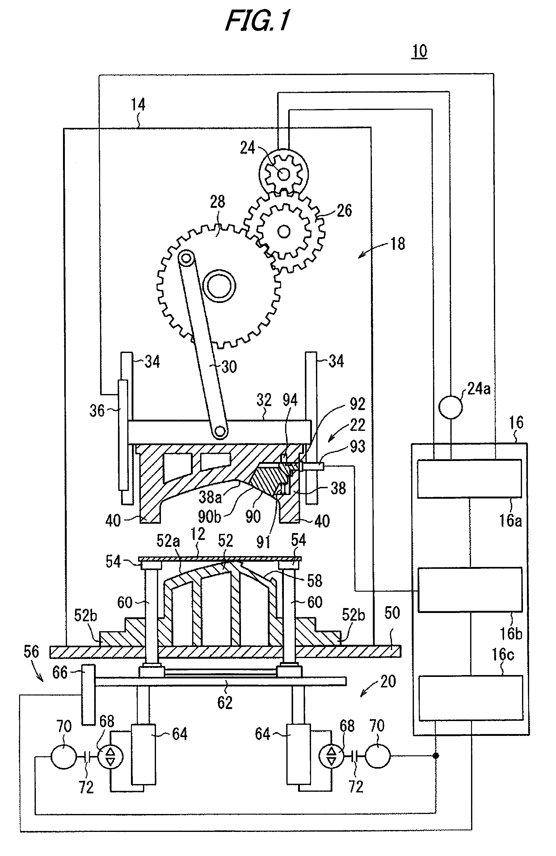
[0056]A press working method and the press working apparatus of a first exemplary embodiment of the present invention will be explained, referring to FIGS. 1 to 13C. In the press working apparatus 10 of the first exemplary embodiment, after press working of the first time has been conducted on a steel plate (plate member) 12 which is a workpiece, press working of the second time, which is an additional working, is conducted.

[0057]As shown in FIG. 1, the press working apparatus 10 includes: an apparatus body 14 for conducting working; and a control portion 16 for controlling the apparatus body 14.

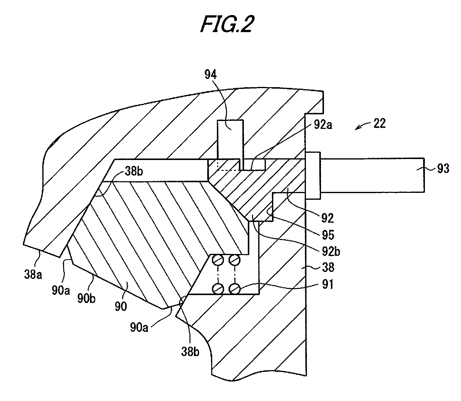
[0058]The apparatus body 14 includes: an upper die mechanism 18; a lower die mechanism 20; and an additional working portion 22 provided inside the upper die mechanism 18. The upper die mechanism 18 includes: a servo motor 24 which is a drive source; a reduction gear 26 driven and rotated by the servo motor 24; a rotary plate 28 driven and rotated by the reduction gear 26 at high torque; and...

second exemplary embodiment

[0113]A press working method and a press working apparatus according to a second exemplary embodiment of the present invention will be explained, referring to FIGS. 14 to 20B. In the press working apparatus 210 of the second exemplary embodiment, press working of a steel plate 212, which is a workpiece, is conducted.

[0114]As shown in FIG. 14, the press working apparatus 210 is provided with: an apparatus body 214 for conducting working; and a control portion 216 for controlling the apparatus body 214.

[0115]The apparatus body 214 is provided with: an upper die mechanism 218; and a lower die mechanism 220. The upper die mechanism 218 is provided with: a servo motor 224 which is a drive source; a reduction gear 226 driven and rotated by the servo motor 224; a rotary plate 228 driven and rotated by the reduction gear 226 at high torque; and a connecting rod 230, the upper end portion of which is pivotally attached onto a side of the rotary plate 228 so that the connecting rod 230 can be...


PUM

PropertyMeasurementUnit
inclination angleaaaaaaaaaa
timeaaaaaaaaaa
speedaaaaaaaaaa

Abstract

In a press working apparatus 10, while a servo motor 24 is acting, an upper die 38 is made to come close to a lower die 52 and press working of the first time is conducted on a steel plate 12. A slider 32 is raised to a movable punch preparation position. A movable punch 90 is protruded from a die face 38a of the upper die 38 by width H and locked by a mechanical lock 94. The upper die 38 is made to come close to the lower die 52 again and the steel plate 12 is pushed with the upper die 38 and at the same time an additional worked portion 12a is pushed and deformed with the movable punch 90 so as to conduct press working of the second time. After the movable punch 90 has been retracted, the slider 32 is raised.

Description

[0001]This application claims foreign priority from Japanese Patent Application Nos. 2006-112242 filed on Apr. 14, 2006, and 2006-112256 filed on Apr. 14, 2006, the entire contents of which are hereby incorporated by reference.BACKGROUND OF THE INVENTION[0002]1. Field of the Invention[0003]The present invention is related to a press working method and a press working apparatus in which a press-formed product is worked by a servo press.[0004]2. Related Art[0005]In a conventional mechanical press, press working is conducted when a slider, which is connected to a crank shaft, is driven upward and downward by a crank shaft rotating motor. In this type mechanical press, since a die is continuously moved upward and downward, it is difficult to change a speed of the die according to a working condition. Further, it is also difficult to temporarily stop the die.[0006]Due to the above circumstances, a servo press has been recently used which can flexibly control a motion of a die with a serv...

Claims


Application Information

Patent Timeline
Patent Type & Authority Applications(United States)
IPC IPC(8): B21D22/21
CPCB21D22/22B21D24/14B30B15/148B21D37/08
Inventor NAGAI, YUICHIMEGURI, HIDEOTAKEDA, KENZOEGAWA, TAKAYUKI
Owner HONDA MOTOR CO LTD
Why Eureka
Try Eureka