

Method and apparatus for repairing vehicles
- Summary
- Abstract
- Description
- Claims
- Application Information
AI Technical Summary
Benefits of technology
Problems solved by technology
Method used
Image

Examples
Embodiment Construction
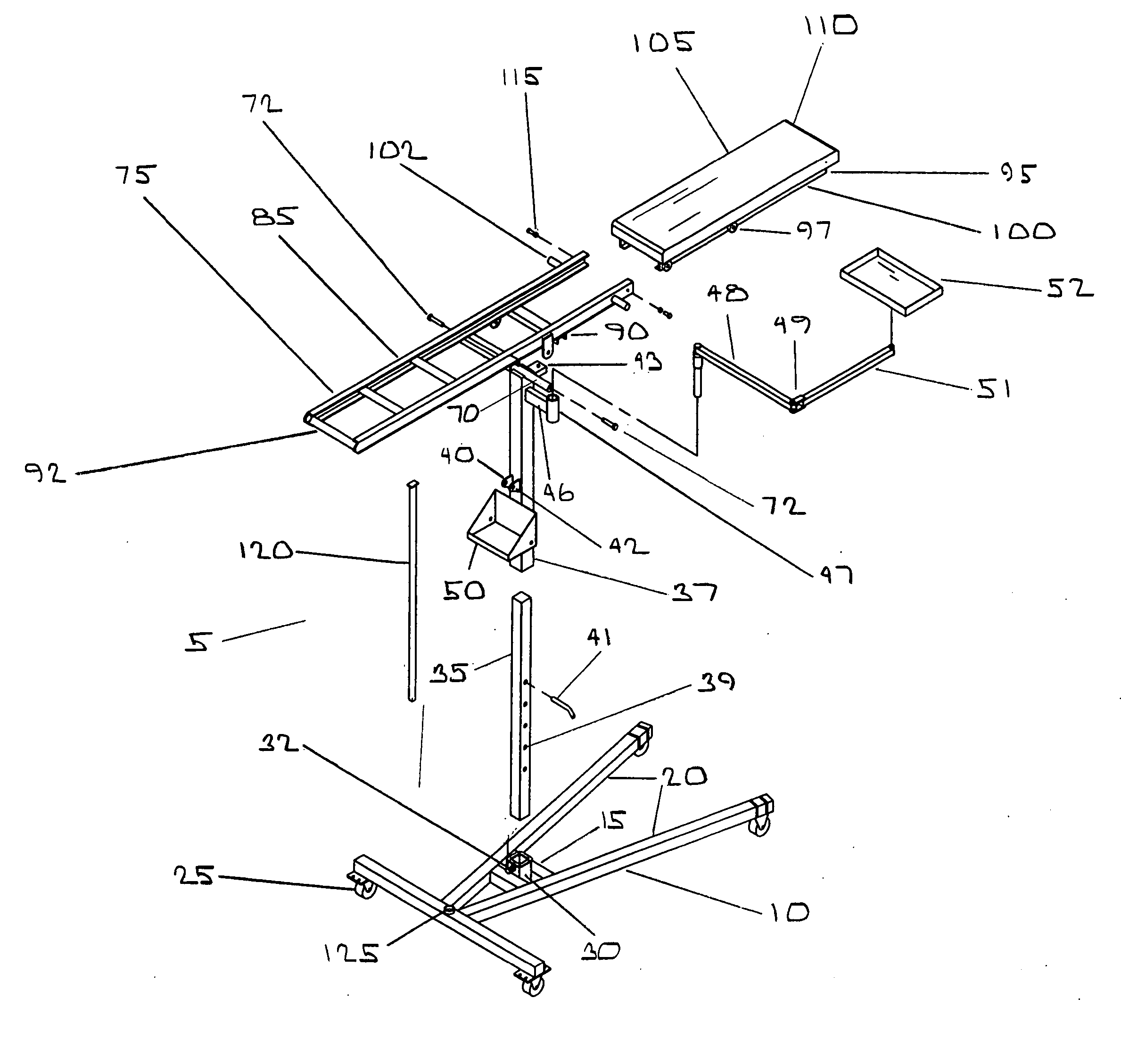
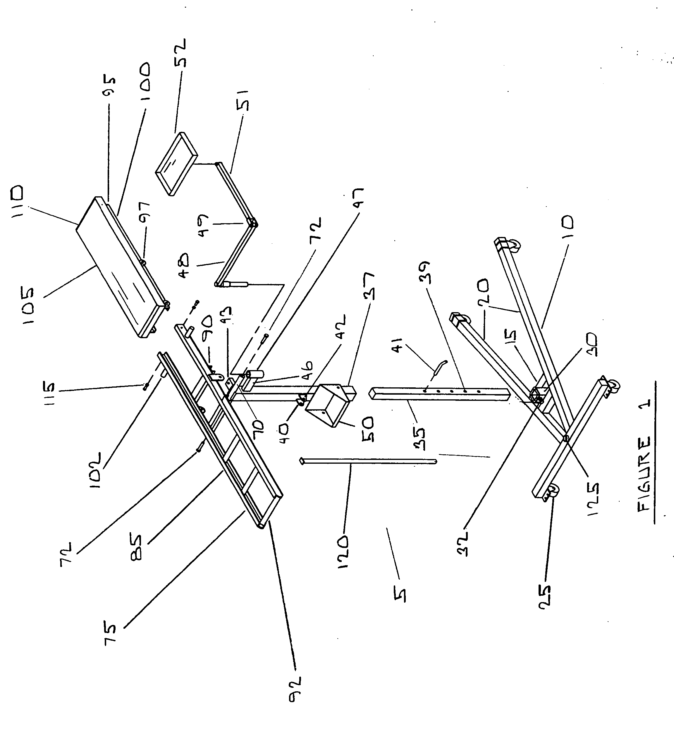
[0023]FIG. 1 references an exploded perspective view showing the invention in detail wherein the invention 5 comprises a movable base structure 10 built preferably with a rigid construction of steel, aluminum or like tubular material welded or otherwise formed to construct a movable base preferably in an a-frame configuration with a central brace means 15.
[0024] Central brace means 15 welded or otherwise mounted to base structure 10 configuration complementary for supporting a central mast 35 as will hereinafter be described. Furthermore central brace means 15 may be formed with any suitable tubular, plate, or channel material complementary with the construction of movable base structure 10 shown in FIG. 1 and 3.
[0025] Said movable base structure 10 constructed of a plurality of substantially identical support member legs 20 comprising elongated longitudinal members furthermore having attached therein a plurality of commercially available wheel 25 or other suitable rolling caster ...
PUM
 Abstract
Description
Claims
Application Information