Three-dimensional pseudo-image presenting apparatus, method therefor and three-dimensional pseudo-image presenting system

a technology of pseudo-image and presenting apparatus, which is applied in the direction of lighting and heating apparatus, semiconductor devices for light sources, instruments, etc., can solve problems such as burning candles, and achieve the effects of high presentation effect, superior safety, and high visual

Inactive Publication Date: 2007-10-18
FLAP +2
View PDF10 Cites 31 Cited by
  • Summary
  • Abstract
  • Description
  • Claims
  • Application Information

AI Technical Summary

Benefits of technology

[0007] An object of the present invention is to provide a three-dimensional pseudo-image presenting apparatus, a method therefor and a three-dimensional pseudo-image presenting which have a high visual effect and a high presentation effect and are superior in safety.
[0015] The present invention is superior in safety because burning candles are not required for presentation. The present invention is adapted to allow persons to see the three-dimensional pseudo-image in all directions around the apparatus with a high visual effect and a high presentation effect, and therefore is effectively usable also in the light emitting instrument industry, the soothing or healing lighting industry, the toy industry, the advertising tower, advertising display and interior industries, the supermarket and convenience-store industries, and so on.

Problems solved by technology

This indicates that the burning candle is one of dangerous factors which cause a fire.

Method used


Image

  • Three-dimensional pseudo-image presenting apparatus, method therefor and three-dimensional pseudo-image presenting system
  • Three-dimensional pseudo-image presenting apparatus, method therefor and three-dimensional pseudo-image presenting system
  • Three-dimensional pseudo-image presenting apparatus, method therefor and three-dimensional pseudo-image presenting system

Examples


embodiment 1

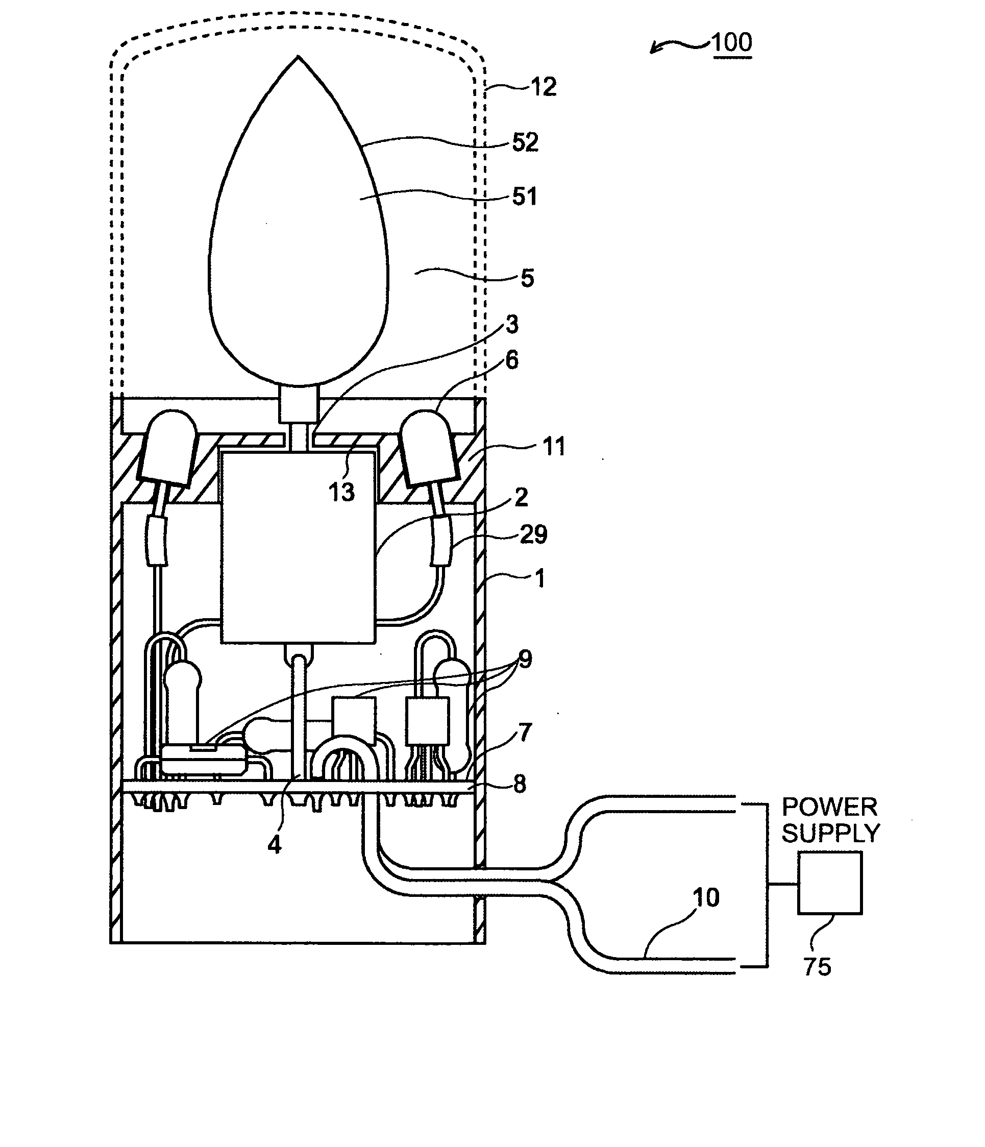
[0032] Referring to FIG. 1, a three-dimensional pseudo-image presenting apparatus 100 comprises a housing-like cylindrical body 1, a motor 2 which functions as a rotary drive source and is secured to the body 1 so as to be arranged therein, a rotating screen unit 5 (which functions as an object of presentation) connected to an output shaft 3 of the motor 2, a light illuminator 6 attached to the body 1 so as to be arranged therein, controller 7, and a power cable 10 connected to an electric power supply 75.

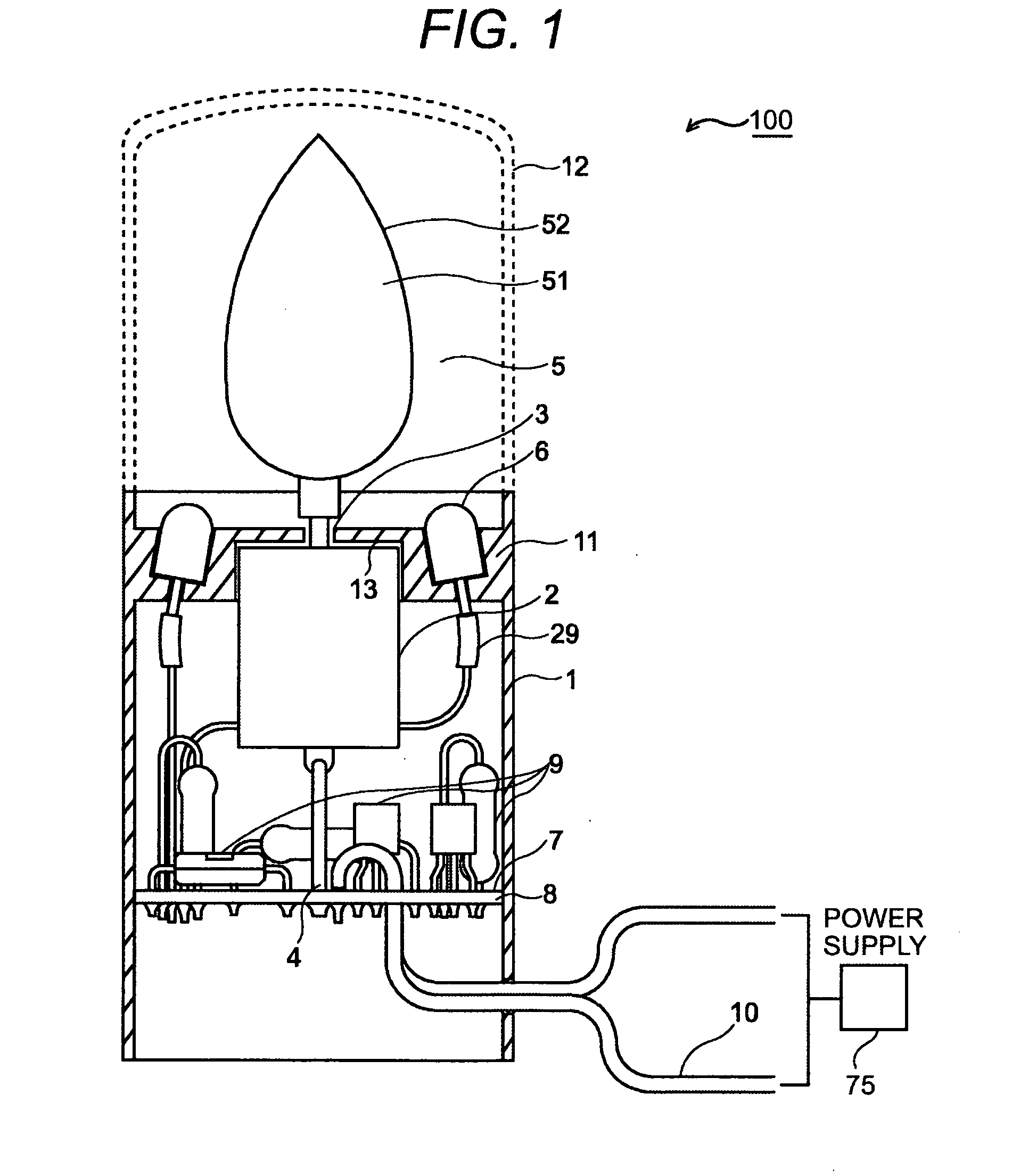
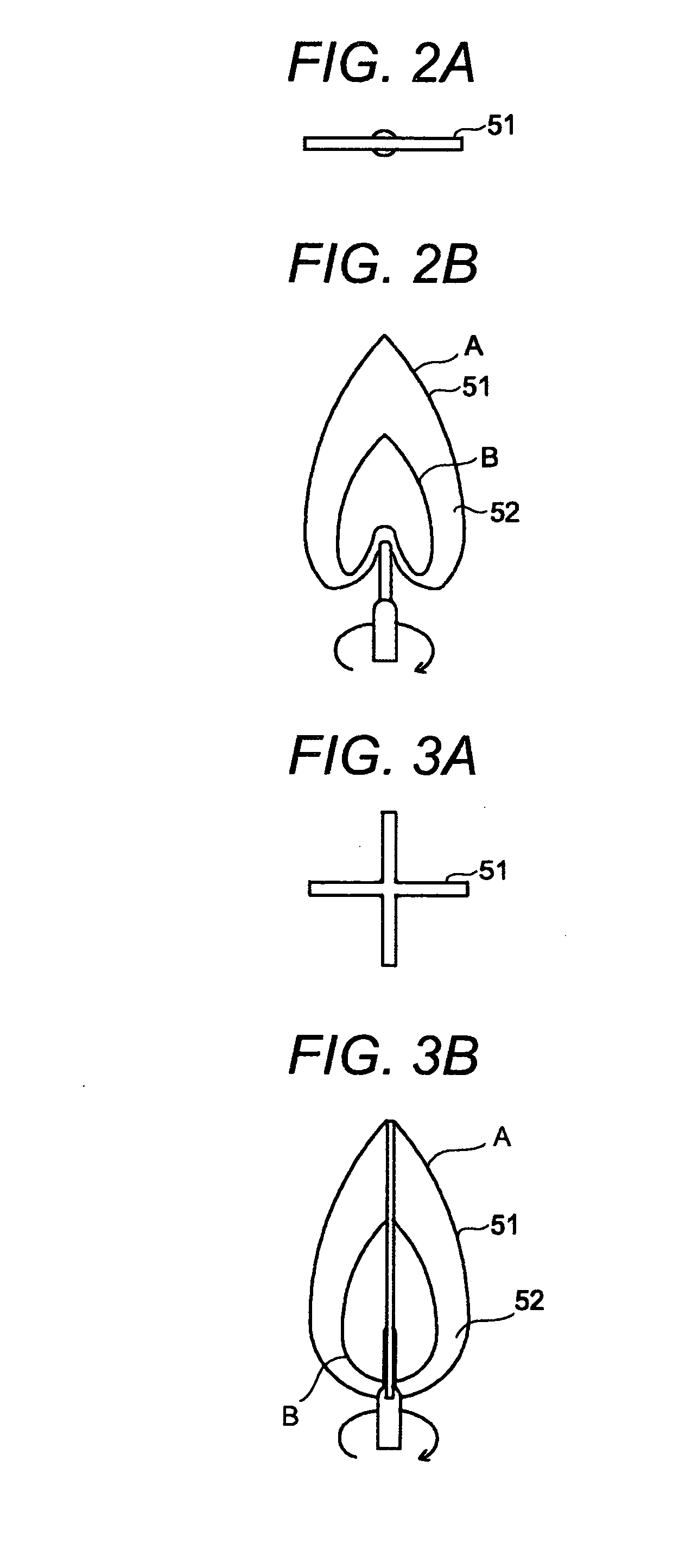
[0033] The rotating screen unit 5 comprises a rotating portion 51 and a presentation character portion 52 provided with a presentation character. The rotating portion 51 and the presentation character portion 52 are formed in one, that is to say, are integrated with each other.

[0034] The rotating portion 51 and the presentation character portion 52 each comprise a thin plate-like member whose shape is similar to a vertical sectional shape of the flame of a burning candle. In this...

examples

[0063] The following table indicates that the magnitude of the flame sway or flickering varies according to whether the presentation character is symmetrical or asymmetrical with respect to the rotation axis of the output motor shaft 3 and whether or not those two portions of the presentation character the boundary of which is defined by the rotation axis of the output shaft 3 are equal in area to each other.

Symmetrical / AsymmetricalAreaFlame flickerAsymmetricalNearly equalSmallAsymmetricalDifferentLargeSymmetricalNearly equalNothing

[0064] If that portion corresponding to the wick of the pseudo-burning candle flame which is drawn on the right and rear surfaces is changed in size so that the wick is changed in thickness, the sway or flickering of the pseudo-burning candle flame in the vicinity of the wick thereof can be changed so that the presentation effect is thereby changed. Therefore, if, in a state where a real candle is burned, the change in brightness of the flame formed the...

embodiment 2

[0072]FIG. 13 shows a three-dimensional pseudo-image presenting apparatus of another embodiment according to the present invention. This embodiment is characteristic in that the body is of a cylindrical light bulb type. In FIG. 13, the same reference numerals as in the other figures indicate the same elements.

[0073] Provided at the opposite end portion of the body 1 to the output shaft 3 is a metal base 31 to be screwed in a light bulb socket for supplying the power. The base metal is connected to an AC / DC converter 32 and further a controller 7.

[0074] When the base metal 31 is screwed in the light bulb socket to which an AC voltage of 100 V (200 V) is applied, the voltage is converted into a DC voltage of about 5 V. The DC converted signal is used for controlling the luminescence and illumination of the illuminator 6 and the number of the rotations of the motor 2.


PUM


Abstract

A presentation character member is rotated on its axis of rotation while being illuminated with light. The presentation character member has a presentation character which is rotated on the axis of rotation of the presentation character member. The presentation character is symmetrical or asymmetrical with respect to a predetermined axis which may coincide with the axis of rotation of the presentation character member. According to the above, a three-dimensional pseudo-image of the presentation character is formed and presented.

Description

BACKGROUND OF THE INVENTION [0001] This invention relates to a three-dimensional pseudo-image presenting apparatus, a method therefor and a three-dimensional pseudo-image presenting system which form and present a pseudo-image three-dimensionally. [0002] In many cases a character is stereoscopically displayed by illumination of the same with light. [0003] Disclosed in Japanese patent application laid-open No. 2004-298471 is a presentation display controlling apparatus comprising a rotor which has its circumferential surface on which patterns are printed and their corresponding light emitting units arranged on a circular locus with a predetermined radius centered on a rotary axis of the rotor, the presentation display controlling apparatus further comprising a control means controlling a first presentation display means which displays the patterns when the rotor is rotated with the light emitting unit turned off and a second presentation display means which displays afterimages of th...

Claims


Application Information

Patent Timeline
Patent Type & Authority Applications(United States)
IPC IPC(8): G01P3/40
CPCF21W2121/00G09F13/04F21S10/04F21K9/23
Inventor KAWAKAMI, KAZUIKUHARA, MASANORI
Owner FLAP
Why Eureka
Try Eureka