Positive-Air-Pressure Machine Conduit

a positive air pressure and machine technology, applied in mechanical equipment, respirators, chemical protection, etc., can solve the problems of limiting the ability of patients to move or roll, adding to the potential discomfort of patients, etc., and achieve the effect of enhancing patient comfor

Inactive Publication Date: 2007-10-25
RESMED LTD
View PDF51 Cites 119 Cited by
  • Summary
  • Abstract
  • Description
  • Claims
  • Application Information

AI Technical Summary

Benefits of technology

[0025] In another embodiment, the material from which each conduit is formed may be adapted to permit the passage of

Problems solved by technology

Such apparatus can tend to limit a patient's ability to move or roll

Method used


Image

  • Positive-Air-Pressure Machine Conduit
  • Positive-Air-Pressure Machine Conduit
  • Positive-Air-Pressure Machine Conduit

Examples


Embodiment Construction

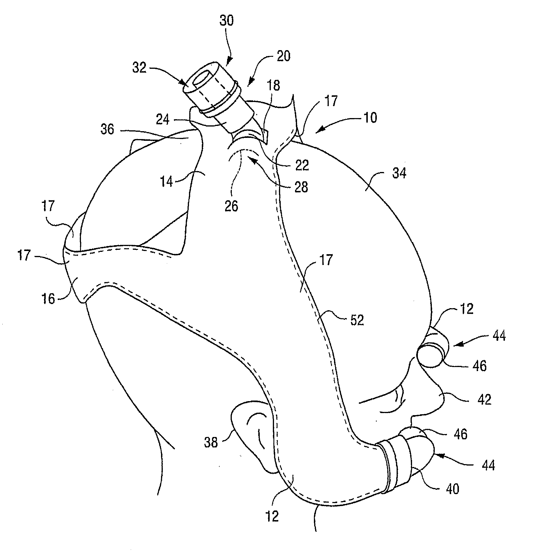
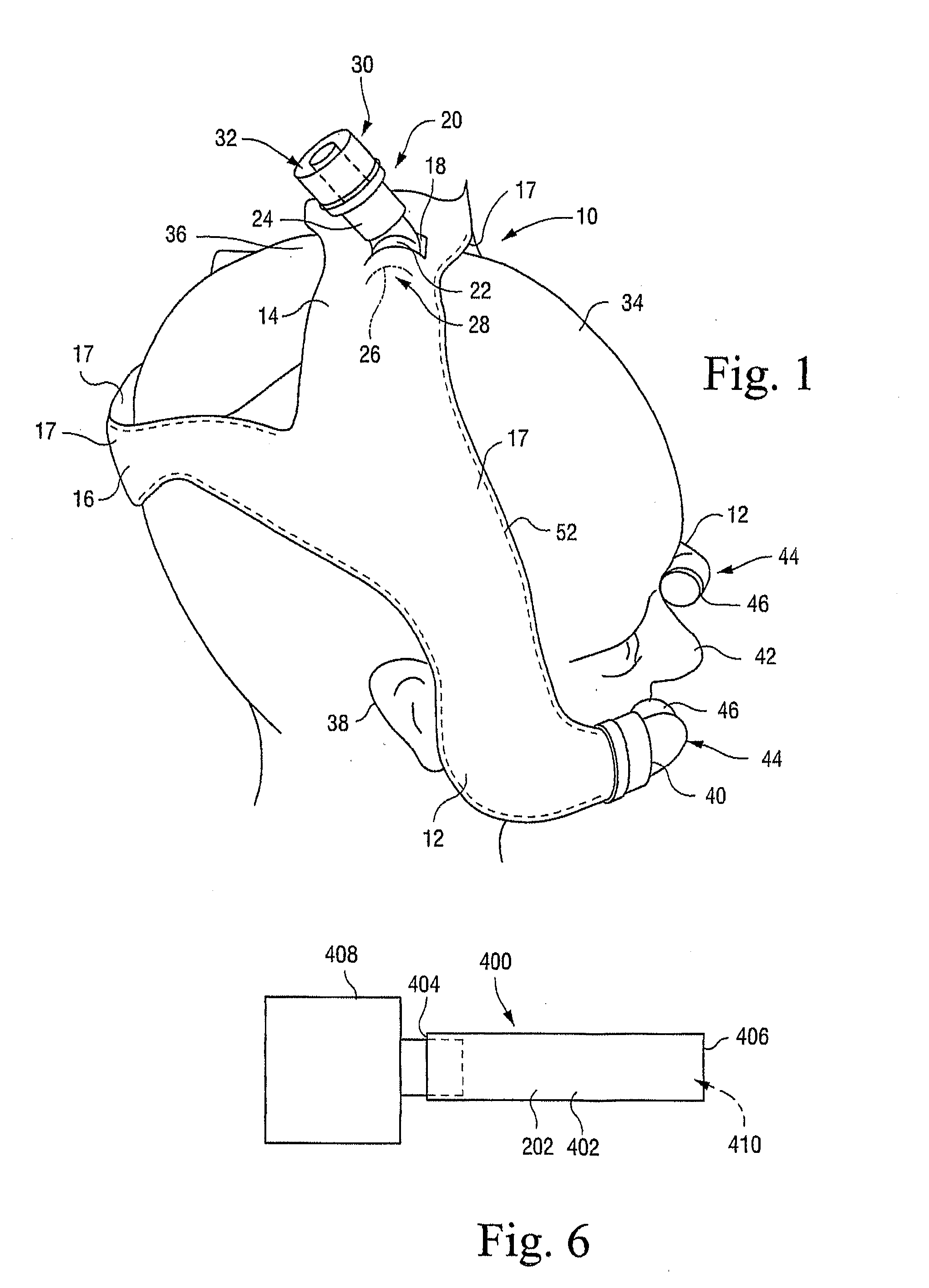
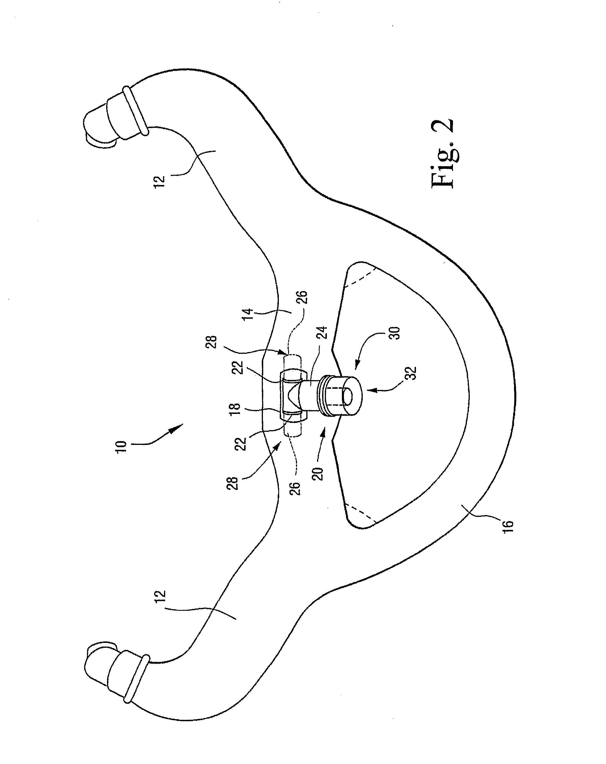
[0071] Referring to FIGS. 1 and 2, there is shown a headgear 10 according to an embodiment of the invention. The headgear 10 includes a pair of conduits or side portions 12 which are joined integrally to each other by a central portion 14. A head attachment means in the form of a strap 16 is also joined integrally to the side portions 12 as shown in FIG. 1, so that the side portions 12, central portion 14, and strap 16 are all of an integral, unitary construction.

[0072] The side portions 12, central portion 14 and strap 16 are formed by joining together, e.g., by high-frequency (HF) plastics welding, a pair of polymeric (e.g., plastic) sheets 17. The manner in which the sheets 17 are joined together is such that the middle portions of the sheets 17 can be parted from each other to define passages running along the length of the side portions 12, as described in more detail below. It will be appreciated that, when the sheets 17 are configured to form such passages in the side portio...


PUM


Abstract

A conduit for delivering a supply of gas under a positive pressure includes a conduit wall having a first conduit end and a second conduit end. The first conduit end is adapted to be attached to the supply of gas. The conduit wall is deformable between an open condition in which the conduit wall defines a conduit passage along which the supply of gas can travel between the first conduit end to the second conduit end, and a collapsed condition in which the conduit wall substantially collapses the conduit passage.

Description

CROSS-REFERENCE TO APPLICATIONS [0001] This application claims the benefit of AU Provisional Application No. 2004902020, filed Apr. 15, 2004, which is incorporated herein by reference in its entirety. FIELD OF THE INVENTION [0002] The present invention relates to a positive-air-pressure (PAP) machine conduit. The present invention also relates to headgear including such a conduit and to nose pieces including such a conduit. BACKGROUND OF THE INVENTION [0003] One of the main factors influencing the success or failure of a patient to adopt a CPAP apparatus used in the treatment of obstructive sleep apnea is the patient's ability to handle the discomfort of the headgear and supply conduit associated with such apparatus. [0004] Such apparatus can tend to limit a patient's ability to move or roll during sleep, thus adding to the potential discomfort for a patient. [0005] Therefore, a need has developed in the art to overcome or ameliorate at least some of the disadvantages of such appara...

Claims


Application Information

Patent Timeline
IPC IPC(8): F16L11/00A62B17/04A61M16/00A61M16/06A61M16/08
CPCA61M16/0666A61M2016/0661A61M16/08A61M16/0683A61M16/0833A61M2205/0238A61M16/0611
Inventor KWOK, PHLLIP RODNEYDARKIN, DONALD
Owner RESMED LTD
Why Eureka
Try Eureka