Assembly for pain suppressing electrical stimulation of a patient's spinal cord

a technology for pain suppression and electrical stimulation, which is applied in the direction of spinal electrodes, internal electrodes, therapy, etc., can solve the problems that the pain suppression assembly of known electrical stimulation typically fails to exhibit one or more of the above described desirable characteristics, and achieves effective reduction and blockage of chronic pain, prevent undesirable buckling or back folding, and enhance patient comfort

Active Publication Date: 2013-12-31
GOEL AMITABH
View PDF42 Cites 1 Cited by
  • Summary
  • Abstract
  • Description
  • Claims
  • Application Information

AI Technical Summary

Benefits of technology

[0007]The paddle head component preferably carries and supports lateral, medial, and oppositely lateral series of electrical contact plates, and the lateral and oppositely lateral plates are preferably pivotally moveable via hinge connections with a medial panel. Contracting pivoting movement of such lateral and oppositely lateral components advantageously allows the paddle head of the assembly to assume a small cross sectional profile which facilitates passage of the paddle head through the bore of a small diameter Tuohy needle.
[0010]Upon extension of a semi-rigid stay through the flexible insulator's hollow bore to engage such socket, the distal end of such stay may impose a pulling or traction force upon the paddle head which prevents undesirable buckling or back folding during insertion. After insertion, the semi-rigid stay may be withdrawn in order to enhance patient comfort.
[0011]A battery powered electric pulse generator of the type conventionally known in the art is preferably supplied, such generator being electrically connected to embedded wire leads which emerge at the extreme proximal end of the flexible insulator. Such pulse generator advantageously supplies pulsating electrical power to the embedded wire leads and to the paddle head's electrical contact plates. Electrical conduction of such electric pulses at a desired location over the patient's spinal cord are known in the neurological arts to effectively reduce and block chronic pain.
[0012]Accordingly, objects of the instant inventive assembly for pain suppressing electrical stimulation of a patient's spinal cord include the provision of a paddle head configuration which includes hingedly interconnected lateral, medial, and oppositely lateral components for compactness during cannulas needle insertion and for alternative augmentation of electrical contact surfaces following insertion and during use. The invention's objects further include the provision of a proximally opening stay end receiving traction socket for prevention of buckling of the paddle head during insertion.

Problems solved by technology

Known electrical stimulation pain suppression assemblies typically fail to exhibit one or more of the above described desirable characteristics.

Method used


Image

  • Assembly for pain suppressing electrical stimulation of a patient's spinal cord
  • Assembly for pain suppressing electrical stimulation of a patient's spinal cord
  • Assembly for pain suppressing electrical stimulation of a patient's spinal cord

Examples


Embodiment Construction

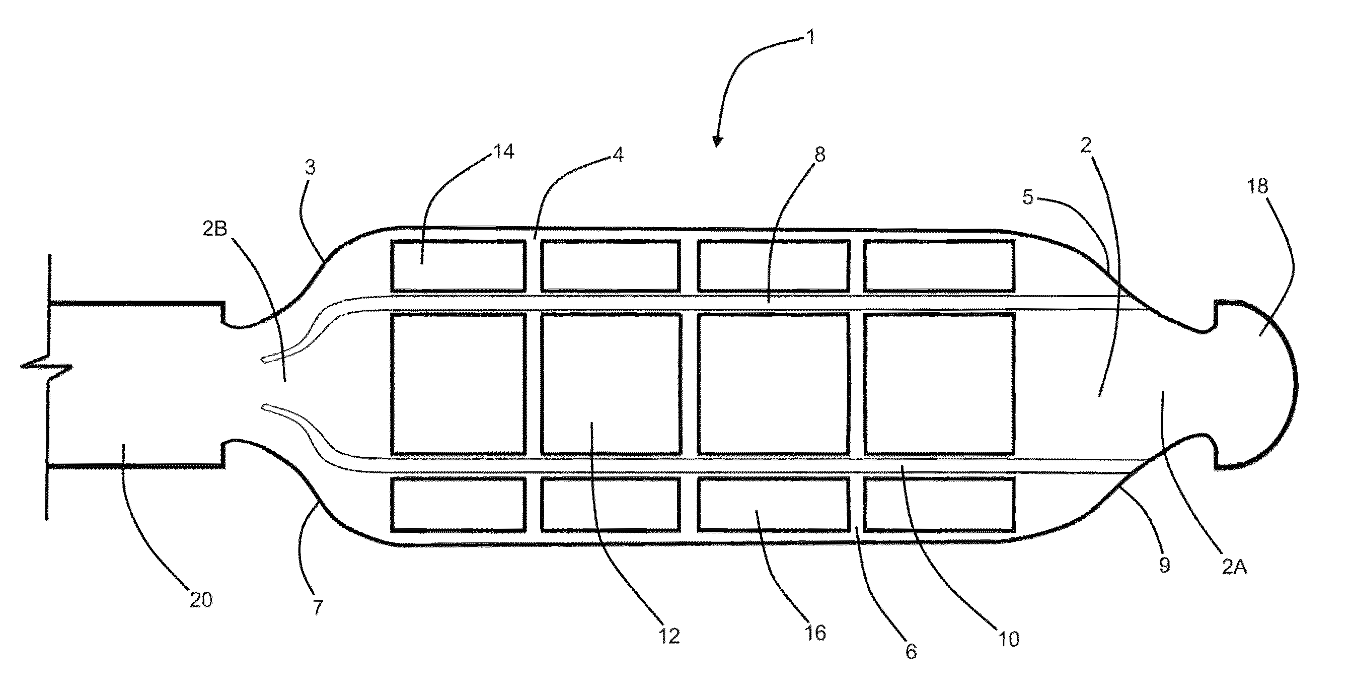
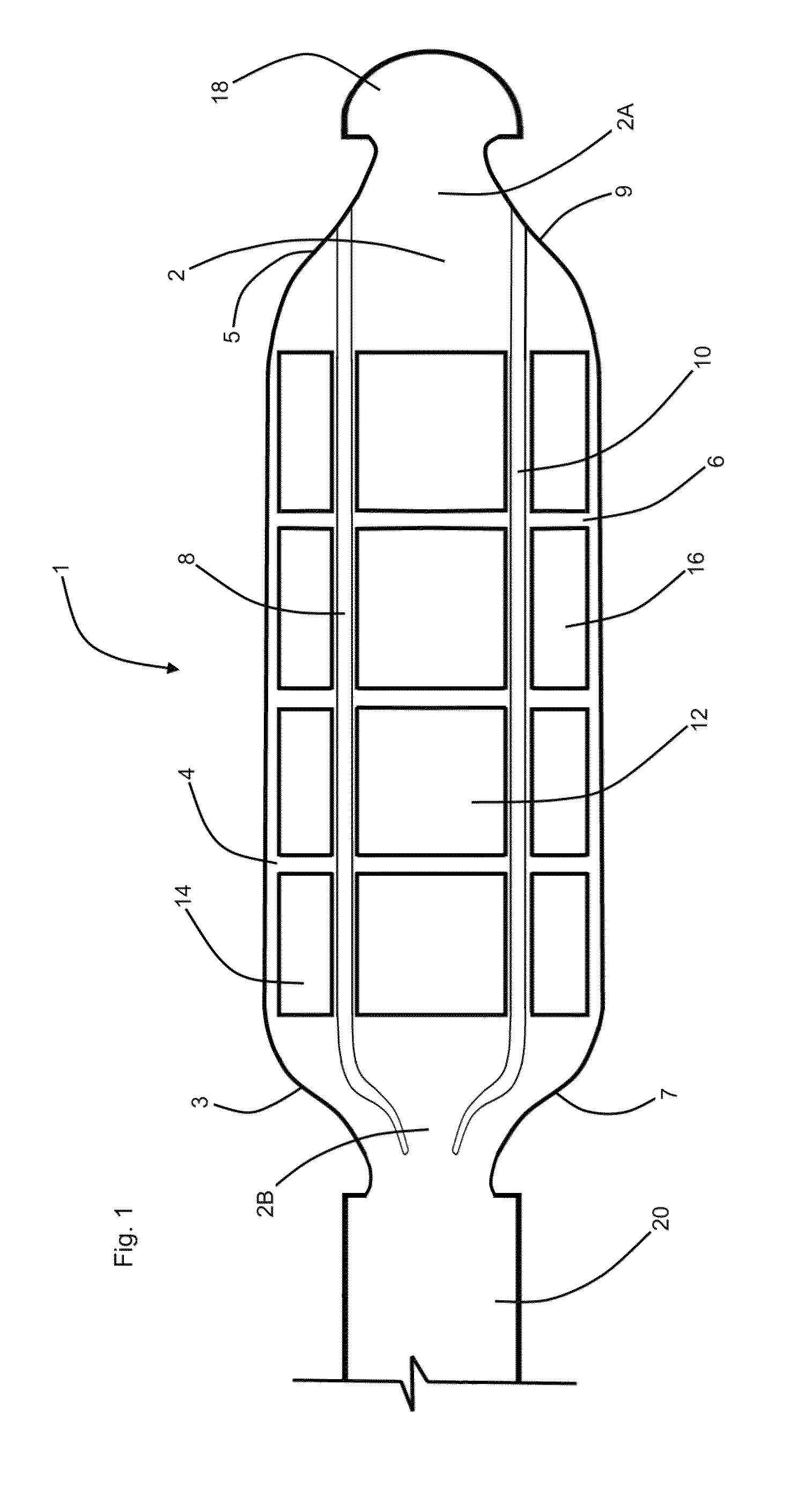
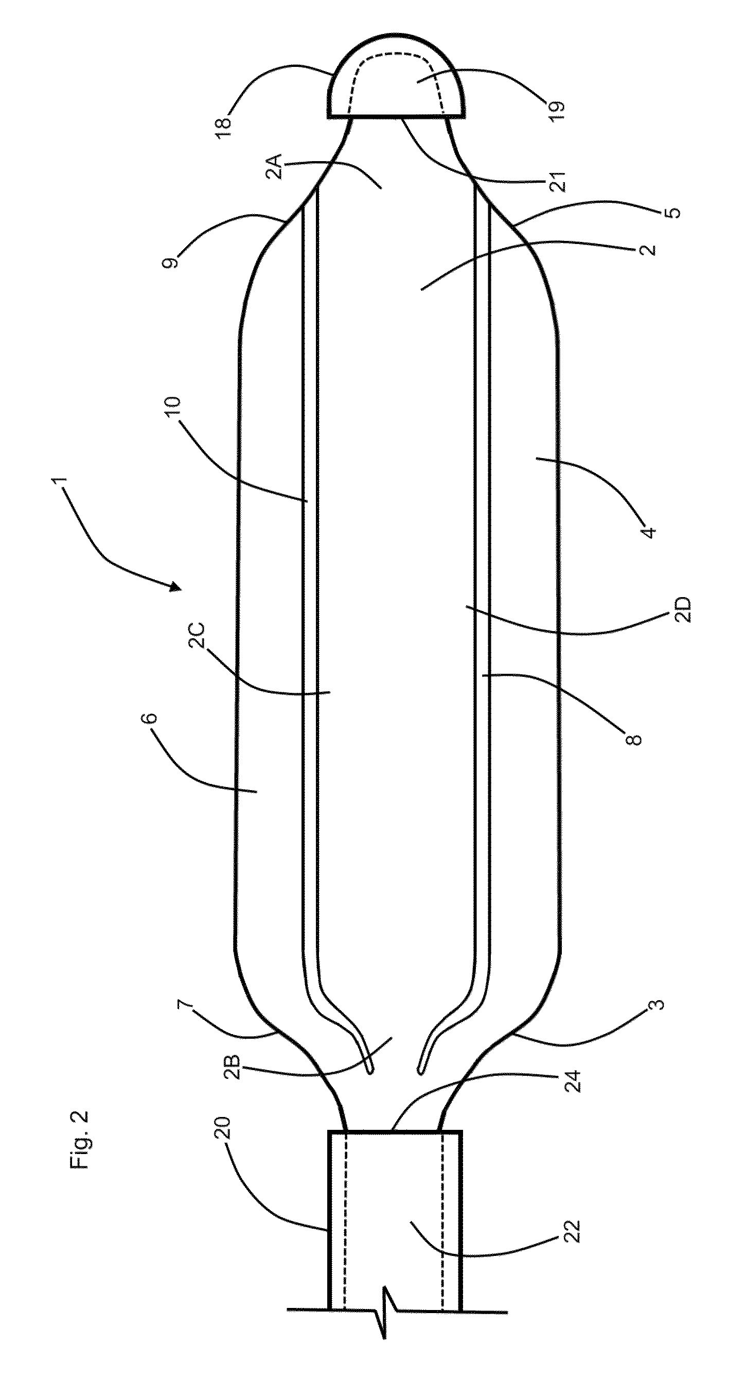
[0020]Referring now to the drawings, and in particular to Drawing FIG. 1, a preferred embodiment of the distal aspects of the instant inventive assembly for pain suppressing electrical stimulation of a patient's spinal cord is referred to generally by Reference Arrow 1. Such assembly 1 preferably comprises at least a first or medial panel which is referred to generally by Reference Numeral 2. Referring further simultaneously to FIG. 2, the at least first panel 2 has a distal end 2A, a proximal end 2B, a lateral side 2C, and an oppositely lateral side 2D. The at least first panel 2 is preferably composed of durable and flexible injection molded plastic which enables the at least first panel 2 to serve functionally as a substrate structure which supports at least a first series or medial series of electrical contact plates 12.

[0021]The at least first or medial series of electrical contact plates 12 are preferably composed of a durable and corrosion resistant electrically conductive me...


PUM


Abstract

An assembly for pain suppressing electrical stimulation of a patient's spinal cord, the assembly including lateral, medial, and oppositely lateral series of contact plates; a lateral panel, a medial panel and an oppositely lateral panel, the electrical contact plates being fixedly attached to the panels; living hinges pivotally attaching the lateral and oppositely lateral panels to the medial panel; proximally extending wires electrically communicating with the contact plates; a proximally extending insulator attached to the medial panel, the insulator having a hollow bore and the wires being embedded within the insulator; a proximally opening traction socket fixedly attached to the medial panel; and a semi-rigid stay which is extendable through the hollow bore, the semi-rigid stay being engageable with the proximally opening traction socket.

Description

FIELD OF THE INVENTION[0001]This invention relates to apparatus and assemblies for pain suppressing electrical stimulation of a patient's spinal cord. More particularly this invention relates to such apparatus which are adapted for percutaneous insertion into and extension along the pain patient's vertebral column.BACKGROUND OF THE INVENTION[0002]Assemblies which are adapted for electrical stimulation of a patient's spinal cord for pain suppression are known to be insertable percutaneously through a cannulas and into the patient's vertebral epidural space. During the performance of insertion procedures, such assemblies desirably exhibit a semi-rigid character within their elongated lead portions and within their electrical contact “paddle” head portions. Following epidural insertion and optimization of paddle head positioning, such assemblies desirably exhibit an alternative flexible and protrusion free character for enhancement of patient comfort during pain suppressing use. In ord...

Claims


Application Information

Patent Timeline
Patent Type & Authority Patents(United States)
IPC IPC(8): A61N1/00
CPCA61N1/0553A61N1/36021A61N1/36017
Inventor GOEL, AMITABH
Owner GOEL AMITABH
Why Eureka
Try Eureka