
Orthodontic bracket and method of attaching orthodontic brackets to teeth

a technology of orthodontic brackets and brackets, applied in the field of orthodontic brackets, can solve the problems of inconvenient use, inconvenient adjustment of bracket positioning, and inability to visualize precise bracket positioning, and achieve the effects of enhancing patient comfort, minimizing visibility, and minimizing size profiles

Active Publication Date: 2012-08-28
REISING BRIAN C
View PDF45 Cites 11 Cited by
  • Summary
  • Abstract
  • Description
  • Claims
  • Application Information

AI Technical Summary

Benefits of technology

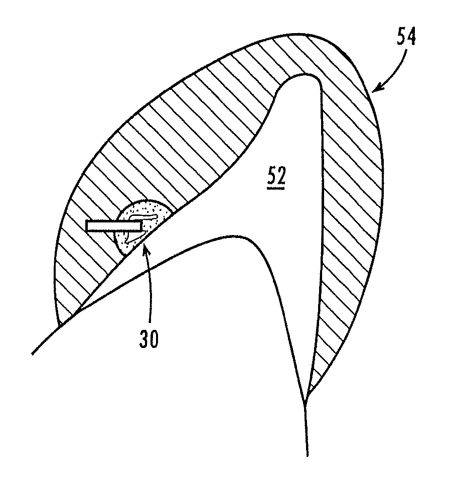
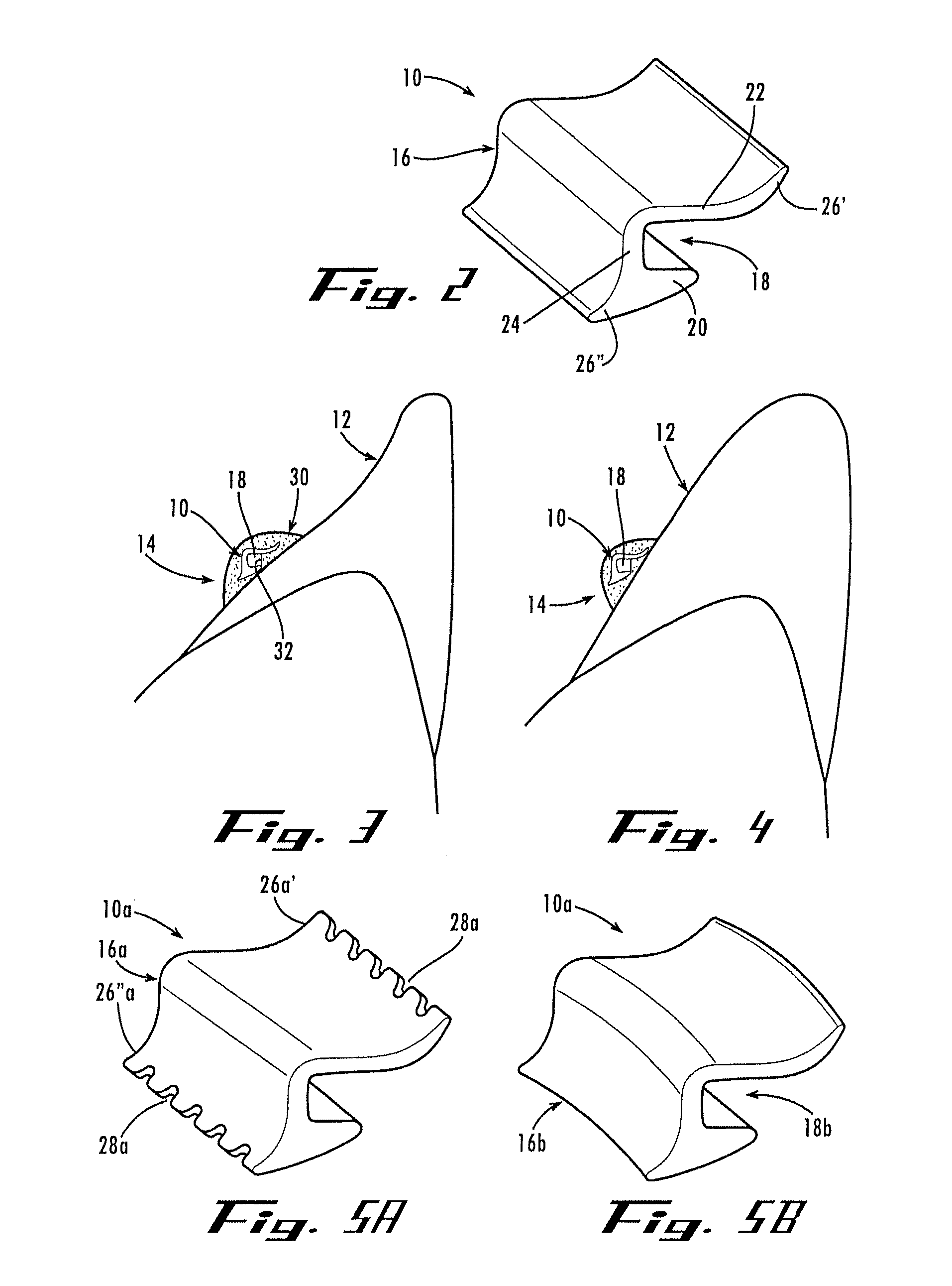
[0030]In alternative embodiments, the bracket has notches or slits that promote enhanced bonding strength, a laterally curved body and opening, two or more of the openings, and / or a tubular opening.
[0033]Still another aspect of the present invention includes a clip for holding an orthodontic bracket having an opening. Generally described, the clip has a finger that is received in the bracket opening and a handle portion for grasping. The finger has a length that is equal to or greater than the length of the bracket opening so that the finger extends all the way through the opening to prevent the adhesive from intruding into and blocking the opening. Preferably, the finger is configured so that it fits snugly in the opening. In this way, the clip can be held by the handle portion and the clip will support the bracket. For example, the finger may have a cross sectional shape and a lateral curvature that conform to a cross sectional shape and a lateral curvature of the bracket opening. In addition, the handle portion is preferably keyed for use with a keyed positioning tool, so that the clip can be consistently aligned when grasping it with the positioning tool.
[0043]Accordingly, the present invention provides orthodontic brackets that have a minimal size profile to enhance patient comfort and that can be placed on the lingual side of teeth to minimize visibility and at the same time are extremely flexible in the positions in which they can be oriented to form orthodontic attachments and appliances. Because of this flexibility, the brackets and methods of attachment can be used to reposition teeth much more quickly and with much less patient discomfort while minimizing visibility of the appliances.

Problems solved by technology

However, it is also readily observed upon closer inspection that these mid-facial surfaces do not exactly line up in a straight line with their long axes residing at identical orientations.
This is recognized as a comparatively laborious, slow, unpredictable, and inefficient method.
But when working directly inside the mouth it is very difficult to visualize precise bracket positioning and extremely cumbersome to utilize measuring instruments for determining vertical position.
Because precise positioning of an entire arch of brackets is the exception rather than the norm, the result is a huge compromise in treatment quality and efficiency.
There are drawbacks to conventional bracket systems, regardless of the attachment method used.
However, their applications are limited to the posterior teeth due to the necessity of threading the wire through the mesial or distal ends.
It would be an impractical endeavor to attempt threading an arch-shaped wire through an entire dental arch starting from the most distal molar.
Not only would the wire initial need to extend into the patients throat but the lack of a continuously consistent degree of curvature of the wire segment would preclude insertion of a wire of significant stiffness.
In addition, the closed-face tube attachment precludes the placement of significant arch-wire bends, therefore, it is only practical if the attachment system is positioned with high precision and coordination.
As such, conventional bracket systems are designed to accommodate one bracket per tooth on either the facial or lingual side, but, as a practical matter, not both.
But a base of any substantial length compromises the ability to custom-coordinate positioning of a bracket in particular ways.
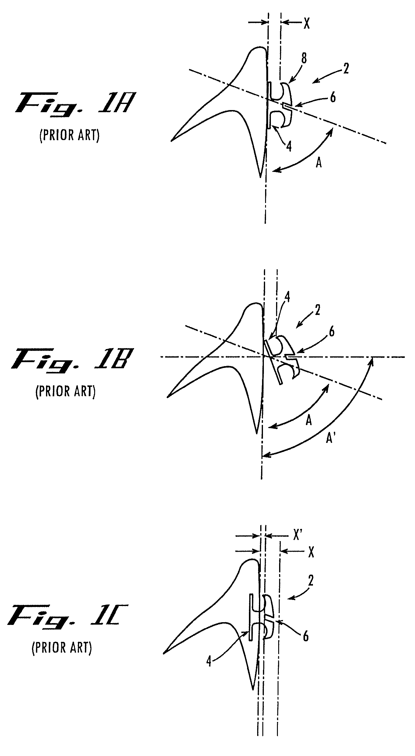
For example, if the operator desires to place the slot at an alternative facio-lingual angle, the base interferes and creates an undesirable lever arm that necessitates displacement of the slot in an unfavorable way, a greater distance from the tooth surface.
And even when the bracket can be positioned with the base flat against the tooth, the width of conventional brackets alone makes them comparably protrusive, when most patients would prefer them to be minimally protrusive.
In addition, because lingual side tooth anatomy is more highly variable among individual tooth types compared with facial side anatomy, using a “base-dependent” positioning system to achieve a “straight-wire” result is even less efficient than the traditional facial bracket system.
That is, a “fixed bracket shape with a base” designed for the lingual tooth surface is remarkably less efficient at achieving coordination of slot positions such that a straight wire could then deflect the teeth to the desired positions.
Because of this inefficiency, greater effort and greater unpredictability are realized by the operator who attempts to bend arch-wire to compensate for poorly coordinated lingual bracket slots.
While this can theoretically be accomplished using a traditional bracket with a base and protruding tie-wings, the degree of protrusion and irregularity of shape (roughness) creates substantial discomfort for the patient.
For this reason and others, lingual bracket systems have seen only very limited applications in orthodontics.
In addition, the desirability of adjustability has lead to the predominant use of open-faced slots.
In fact, open-faced slots are a practical necessity because of the obvious problem that a wire possessing compensating bends of significant size cannot be threaded through tubes of small cross-section and the obvious problems with insertion of full-length arch-wires through a closed-face bracket system.
And the tie-wings create a relatively bulky, high profile bracket system and generally result in a highly irregular surface against which lips, cheeks, and tongue will rub and create discomfort.
Because of the cost associated with the vast inventory of brackets required, most operators use a manufacturer-specified shape (not a shape customized to the unique dental anatomy of the patient) for each tooth.
Existing brackets do not allow for minimizing the profile and protuberances, which would create a far more comfortable lingual bracket system.
The necessity of having tie-wings to engage ligature ties for the purpose of holding the wire engaged in the slot means that uncomfortably large, irregular protuberances are unavoidable.

Method used


Image

  • Orthodontic bracket and method of attaching orthodontic brackets to teeth
  • Orthodontic bracket and method of attaching orthodontic brackets to teeth
  • Orthodontic bracket and method of attaching orthodontic brackets to teeth

Examples


Embodiment Construction

[0111]Referring to the drawings, FIGS. 1A-C illustrate a conventional prior art orthodontic bracket 2. The bracket has a flat base 4 with a large surface area for bonding to a tooth, a rectangular slot 6 for a rectangular wire, and tie wings 8 for tying down the wire in the slot. Once the base 4 is positioned against the tooth, the orientation and position of the slot 6 are fixed and cannot be easily customized. In particular, the bracket 2 cannot be easily rotated to adjust the angle A of the slot 6 relative to the tooth, for example, to an increased angle A′, without the base 4 acting as a lever arm that increases the in / out position of the slot relative to the tooth (see FIG. 1B). And the bracket 2 cannot be moved horizontally to adjust the in / out position X of the slot 6 relative to the tooth, for example, to a decreased in / out position X′, because of interference with the tooth (see FIG. 1C). As such, the bracket slot 6 is offset a good distance from the tooth surface, giving t...


PUM


Abstract

An orthodontic bracket having an opening for receiving a wire, but without a base to create a lever arm when the bracket is oriented in free space at a customized angle relative to a tooth surface. The bracket can be embedded into or encapsulated by an adhesive that is bonded to the tooth. A clip is provided for holding the bracket in position and occluding the opening while the adhesive is applied. And indirect methods of attaching the brackets to teeth are provided wherein the brackets can be attached to the lingual side of the teeth in a low-profile arrangement. A first method includes the step of positioning the brackets on a physical model of the teeth by using a positioning machine. A second method includes the step of positioning virtual brackets on a virtual model of the teeth using software, then generating a physical transfer try using rapid prototyping.

Description

CROSS-REFERENCE TO RELATED APPLICATION[0001]This application is a continuation-in-part of U.S. patent application Ser. No. 10 / 749,918, filed Dec. 31, 2003, and U.S. patent application Ser. No. 10 / 10 / 750,194, filed Dec. 31, 2003, both of which claim the priority benefit of U.S. Provisional Patent Application Ser. No. 60 / 437,546, filed Dec. 31, 2002, and this application claims the priority benefit of U.S. Provisional Patent Application Ser. No. 60 / 742,311, filed Dec. 5, 2005, which in their entirety are herein incorporated by reference.TECHNICAL FIELD[0002]The present invention relates generally to dentistry and orthodontics and, in particular, to attaching orthodontic brackets to teeth for repositioning the teeth.BACKGROUND OF THE INVENTION[0003]Orthodontists commonly correct the position of mal-occluded and mal-aligned teeth by therapeutic tooth movement. Therapeutic tooth movement is accomplished by the application of force to teeth to reposition them. Many orthodontic appliances ...

Claims


Application Information

Patent Timeline
Patent Type & Authority Patents(United States)
IPC IPC(8): A61C3/00
CPCA61C7/145A61C7/146A61C7/002B33Y80/00A61C7/02
Inventor REISING, BRIAN C.HATZILIAS, GIORGOS
Owner REISING BRIAN C
Learn More