Reinforced Retention Structures

a retention structure and reinforcement technology, applied in the field of reinforced retention structures, can solve the problems of limiting the size of the hole that can be formed, failure of the known anchoring mechanism used in medical devices, etc., and achieve the effect of reducing retention strengths and enhancing patient comfor

Inactive Publication Date: 2007-05-31
BOSTON SCI SCIMED INC
View PDF43 Cites 8 Cited by
  • Summary
  • Abstract
  • Description
  • Claims
  • Application Information

AI Technical Summary

Benefits of technology

[0004] Known anchoring mechanisms used with medical devices can fail. For example, internal forces from involuntary bodily functions (such as peristalsis and other secretory forces, as well as patient movement) can force the device out of its intended position within the body. In addition, doctors typically recommend catheter and stent anchoring or retention structures fabricated from softer materials to enhance patient comfort. These softer materials generally have lower retention strengths as compared to more rigid materials. Also, the lower strengths of these softer materials limit the size of holes that can be formed in the medical device to help drain fluid from the body of a patient.
[0005] The present invention provides significantly increased strength to retention structures while also maintaining patient comfort. With the invention, softer materials can be used to maximize patient comfort, and reinforcement of these soft materials affords greater retention properties. Examples of devices that can include retention structures according to the present invention include, but are not limited to, a drainage catheter, a ureteral stent, a urethral stent, a biliary stent, and a prostatic stent.
[0009] In some embodiments, at least one large drain hole slot is formed through the wall of the retention structure. The use of the elastic member in the retention structure eliminates the risk that the retention structure will collapse on itself because of the size of the drain holes. Alternatively or additionally, the elastic member may extend into the elongated member. Because of the stability provided by this configuration, a large drain hole slot may be cut into the elongated member in place of typical smaller drain hole configurations. Also, the elastic member increases the radiopacity of at least the retention structure, thereby enhancing the locatability of the device (or at least the retention structure) using fluoroscopy.
[0010] The extension of the elastic member into the elongated member also enhances pushability of the device during insertion into a body of a patient. The elastic member prevents the device from kinking as it moves within the body. In one embodiment, the elastic member may be removable from the elongated member after insertion. Under this construction, two separate elastic members reside in the retention structure and the elongated member. The length of the elastic member disposed in the elongated member exceeds the length of the device. After insertion of the device into the body of the patient, the operator proximally pulls the elastic member residing in the elongated member from the patient's body. The elastic member residing in the retention structure remains in place.
[0013] In other embodiments, one or more elastic rings radially protruding from the elongated member and containing a reinforcing superelastic ring and a flexible material may be formed or disposed along the elongated member as a retention structure. By varying the size of the rings, the device can accommodate body cavities of different shapes and sizes and work in maintaining the lumen of the tube wide open. The elastic ring or rings may be constructed from a variety of flexible materials, such as elastomeric compounds. Materials like these combine rigidity and the softness necessary for patient stability and comfort.

Problems solved by technology

Known anchoring mechanisms used with medical devices can fail.
Also, the lower strengths of these softer materials limit the size of holes that can be formed in the medical device to help drain fluid from the body of a patient.

Method used


Image

  • Reinforced Retention Structures
  • Reinforced Retention Structures
  • Reinforced Retention Structures

Examples


Embodiment Construction

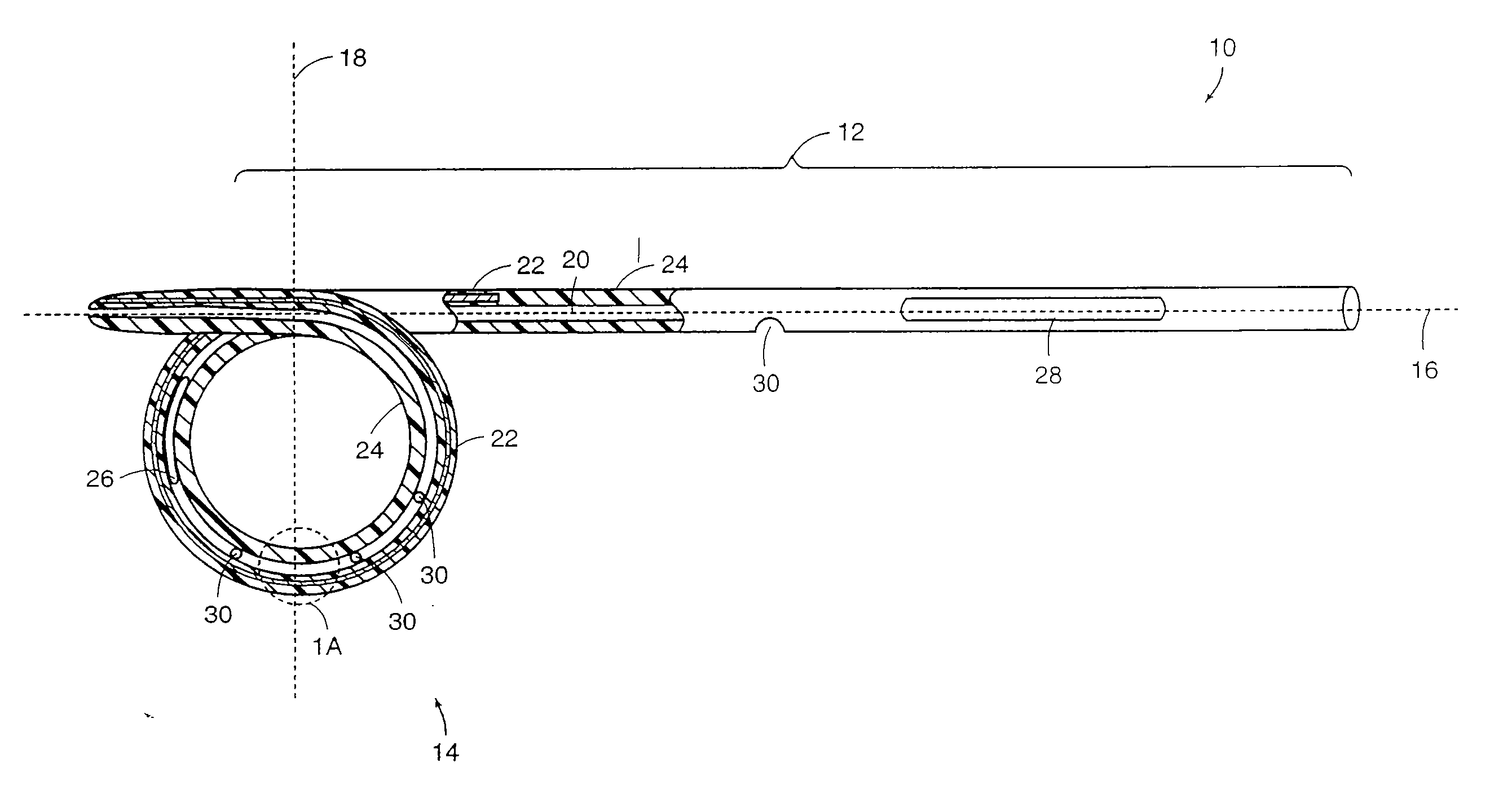
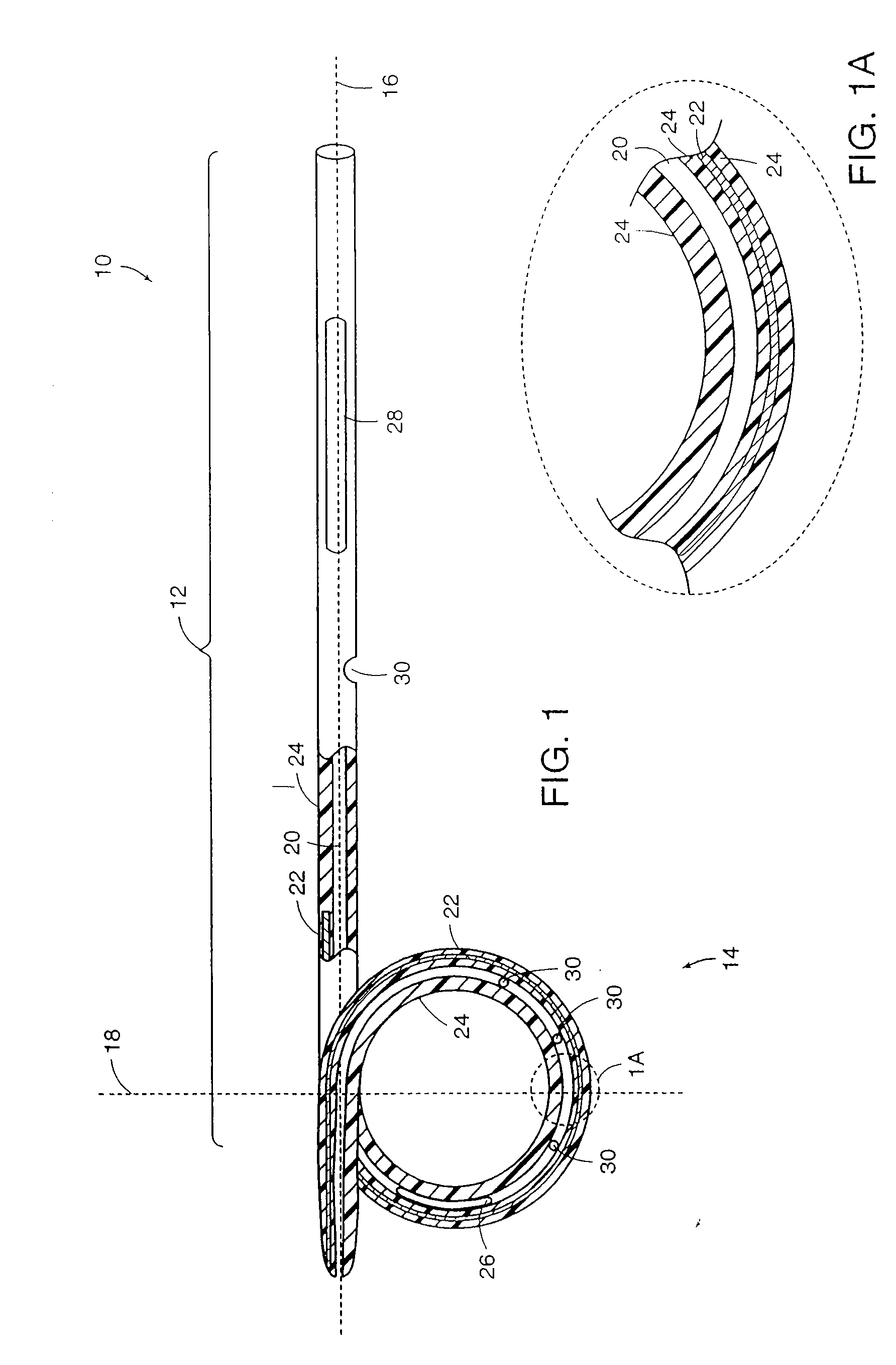
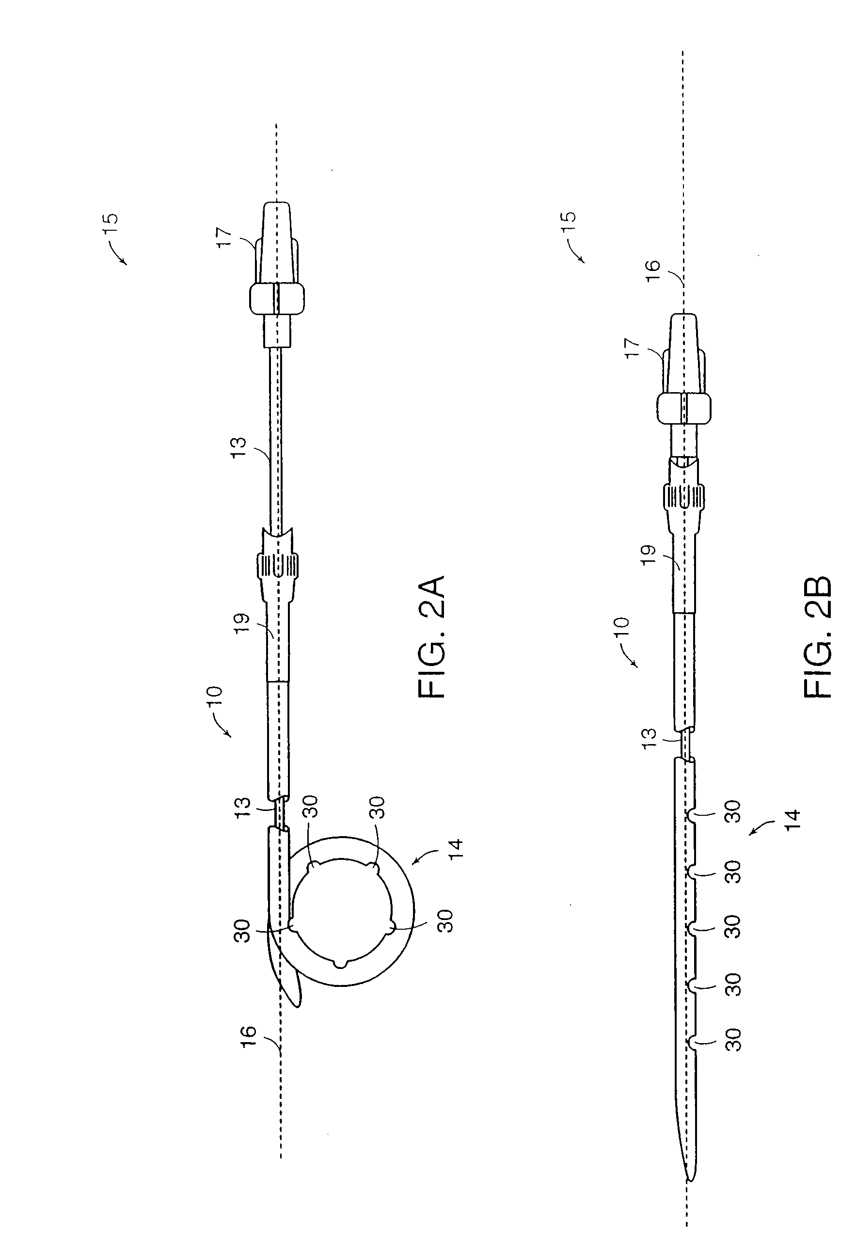
[0033] Medical devices of the present invention are generally constructed of an elongated member and a reinforced retention structure. The elongated member includes a flexible material and the reinforced retention structure includes the same or a different flexible material with an elastic member embedded within or bound to a surface or groove of the flexible material. Preferred materials for the flexible material include, but are not limited to plastic, silicone, TEFLON®, and other PTFE polymers, polyurethane polymers and the like. These materials may also be provided with radiopaque portions to assist in the implantation of the devices in a body of a patient under fluoroscopic monitoring.

[0034] The elongated member may be tubular or conical or a combination of both. Generally, the elongated member comprises a lumen extending through the entire length of the elongated member to provide drainage of fluid from a body cavity. Alternatively or additionally, drainage may be provided or...


PUM


Abstract

A medical device includes an elongated member and a reinforced retention structure. The device can be used for draining substances from organs or abscessed areas within a body of a patient. The elongated member is made of a flexible material. The reinforced retention structure extends from or is formed integrally with the elongated member and comprises an elastic member and the flexible material. The reinforced retention structure provides retention strength while providing flexibility and patient comfort. The use of the reinforced retention structure also provides increased stability to the device within the patient's body and combats migration and / or expulsion of the device. The nature of the reinforcement in the retention structure may extend into the elongated member, which allows for larger drainage openings in the device and increases the radiopacity of the device.

Description

[0001] This application is a continuation of U.S. application Ser. No. 10 / 411 / 606, entitled Reinforced Retention Structures, filed on Apr. 10, 2003, which is a continuation of U.S. application Ser. No. 09 / 829,705, filed Apr. 10, 2001 (now U.S. Pat. No. 6,569,150), which claims the benefit of U.S. Provisional Application Ser. No. 60 / 195,995, filed Apr. 11, 2000, the disclosures of which are incorporated herein by reference.BACKGROUND [0002] Medical devices used for draining fluids from body cavities are generally made of plastic tubing. The tubing is often pre-formed on one or both of its ends to a geometry designed to maintain or anchor the device in position within the body. Medical devices of this type are commonly placed through a ureteroscope, laprascope, or endoscope and into lumens and / or body orifices. In the case of abscess catheters, placement generally occurs percutaneously through a puncture of the external dermis and musculature. In most cases, however, a guidewire is fi...

Claims


Application Information

Patent Timeline
Patent Type & Authority Applications(United States)
IPC IPC(8): A61M25/00A61M25/04A61M25/16
CPCA61M25/04A61M27/002A61M27/008A61M2210/1078
Inventor TEAGUE, JAMES A.BOTTCHER, BENJAMIN J.
Owner BOSTON SCI SCIMED INC
Why Eureka
Try Eureka