Adjustment structure of chair backrests

a backrest and adjustment technology, applied in the field of chairs, can solve the problems of not being able to apply every adjustment, high assembly cost, complicated components, etc., and achieve the effect of reducing cost, simple components, and convenient us

Inactive Publication Date: 2007-10-25
HUNG CHING LIN
View PDF26 Cites 20 Cited by
  • Summary
  • Abstract
  • Description
  • Claims
  • Application Information

AI Technical Summary

Benefits of technology

[0010] 1. The adjustment structure of the chair backrest disclosed in the present invention has a sliding end 50 with zigzag positioning groove 51, a guided sliding seat 60, a positioning component 70 and a resilience component 80, which achieves the preferred practicability. The structure has simple components and greatly reduced cost, so that it can be used to adjust the head rest of the chair backrest, width of the chair backrest, and the moving forward and backward of the chair backrest.
[0011] 2. The positioning is achieved by locking the peg 73 of the positioning component 70 in the zigzag positioning groove 51 to makes the positioning stable.
[0012] 3. The adjustment structure of the present invention can be positioned and adjusted by pressing, moving or pushing the positioning component 70, which makes the operation effective and convenient.
[0013] The new effect of the present invention is described as follows:
[0014] By the design of the resilient support 90 between the sliding end 50 of the curved bottom frame 11 and the seat cushion 40, the sliding end 50 becomes more resilient, which makes the forwarding movement of the curved bottom frame 11 much easier.

Problems solved by technology

The conventional chair backrest adjustment has problems such as complicated components and high assembly cost.
Therefore, if the conventional structure is used with this special backrest, one of the problems will be that not every adjustment can be applied.
The second problem is that the cost of the manufacturing would increase dramatically, which is not practical.

Method used


Image

  • Adjustment structure of chair backrests
  • Adjustment structure of chair backrests
  • Adjustment structure of chair backrests

Examples


Embodiment Construction

[0033] The features and the advantages of the present invention will be more readily understood upon a thoughtful deliberation of the following detailed description of a preferred embodiment of the present invention with reference to the accompanying drawings.

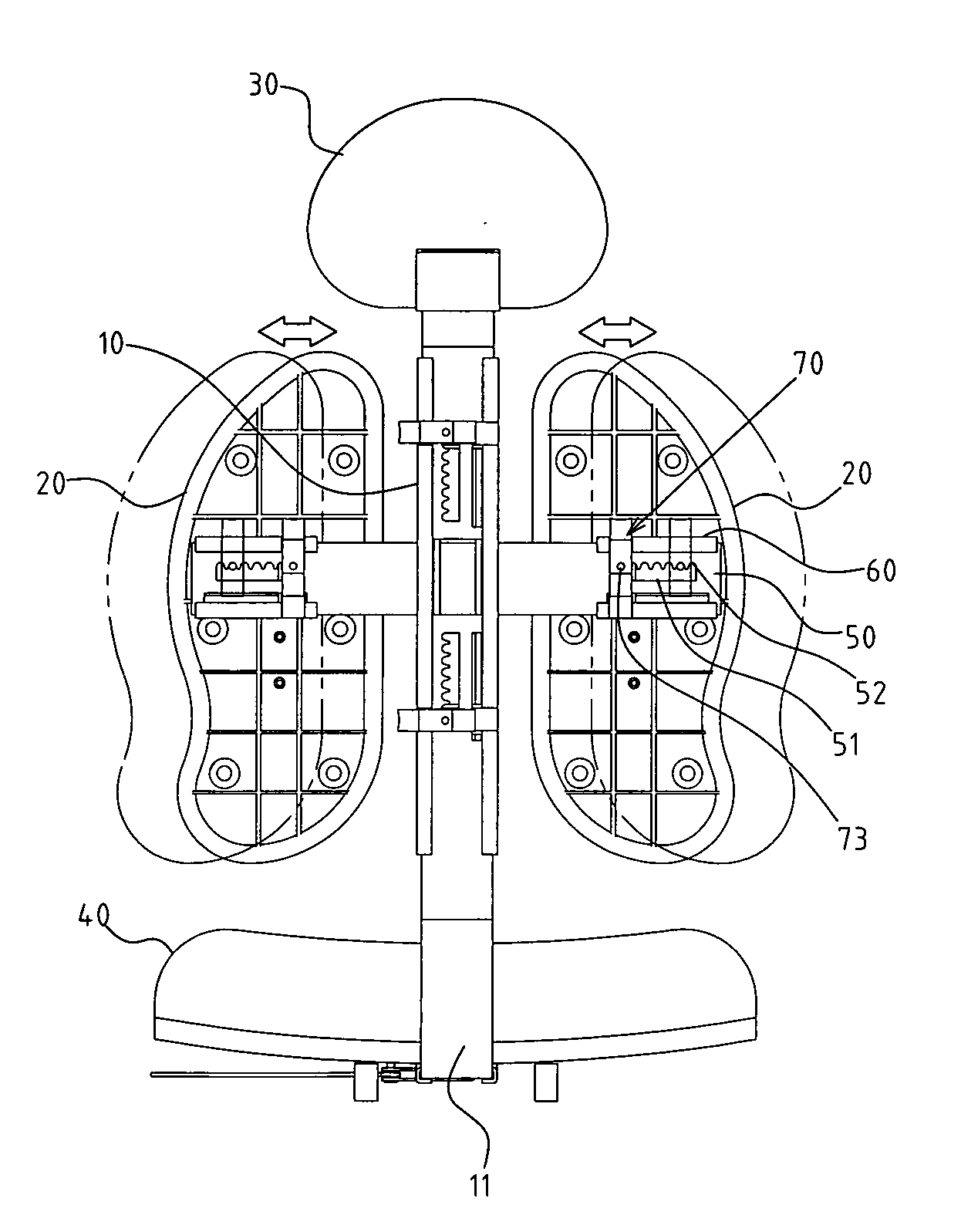
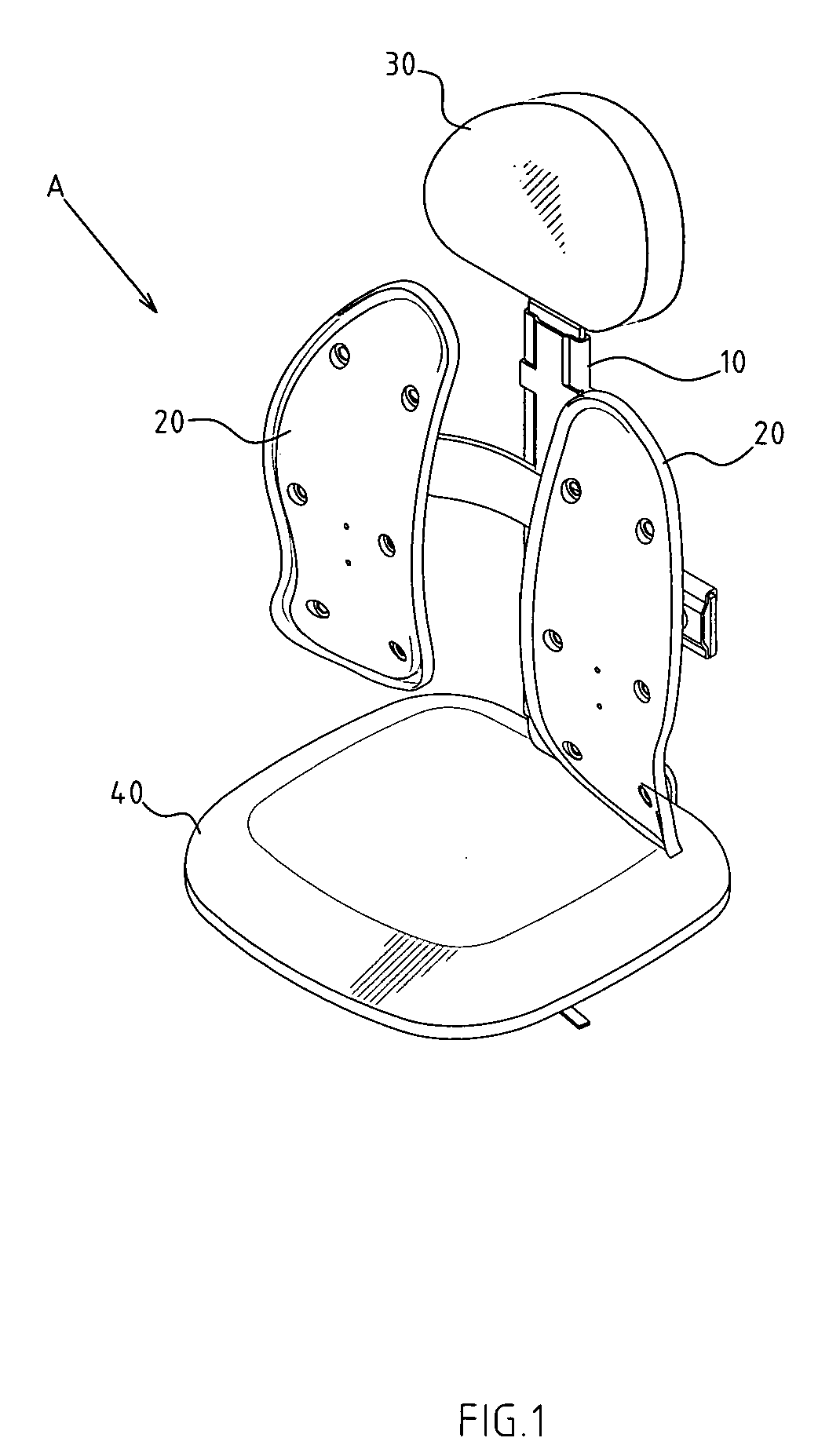
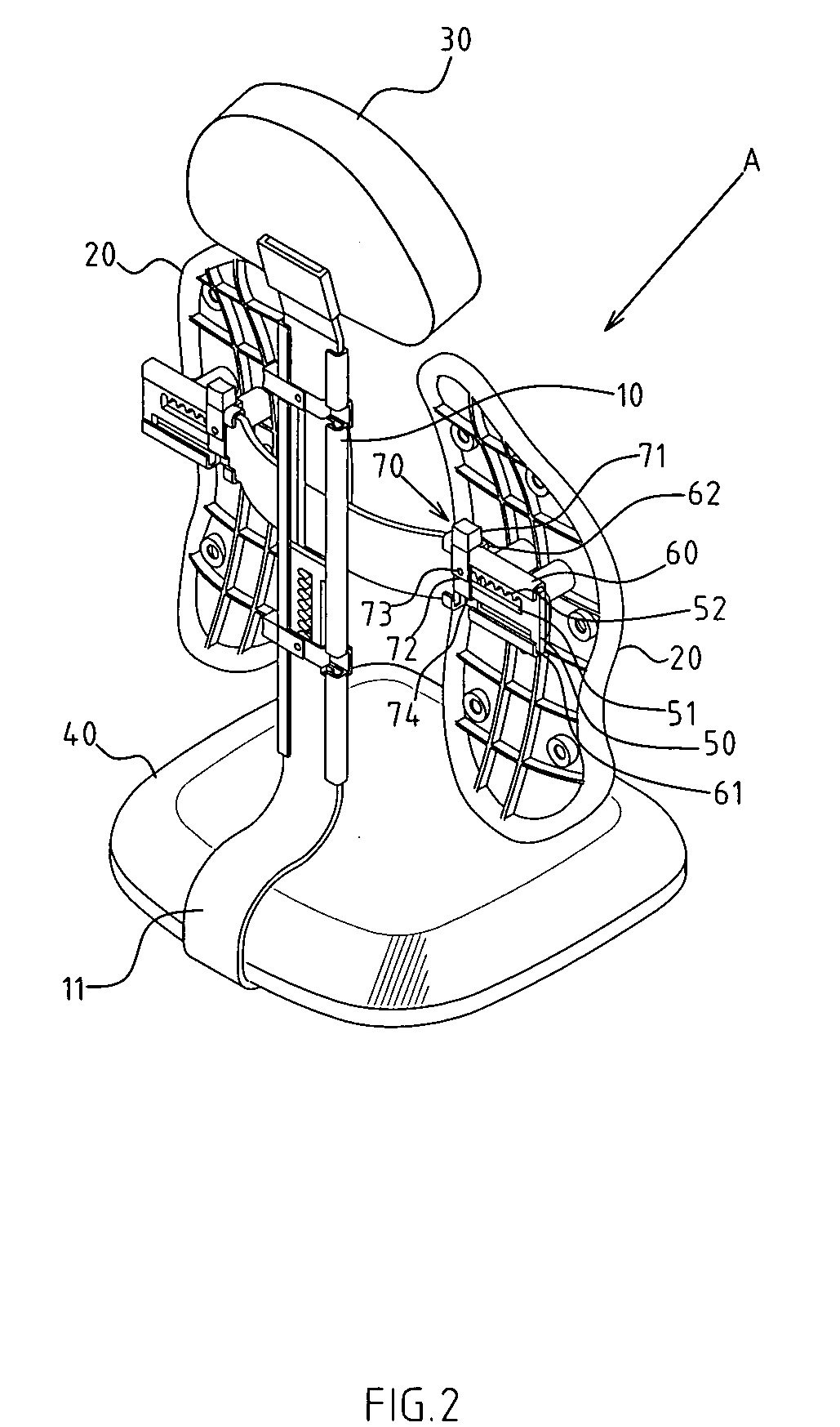
[0034] As shown in FIGS. 1-3, there is an adjustment structure of the chair backrest described in the present detailed description of the present invention based on a typical preferred embodiment. Although the invention has been explained in relation to a preferred embodiment, it is to be understood that many other possible modifications and variations can be made without departing from the spirit and scope of the invention as hereinafter claimed.

[0035] The adjustment structure of the chair backrest mentioned herein is placed on the first and second parts on the chair backrest, and the present invention uses a double-acting type chair backrest to describe that adjustment structure applied to all parts of the chair backrest. A...


PUM


Abstract

The present invention provides an adjustment structure of the chair backrest. The adjustment structure includes a sliding end of the first part of the backrest, and the guiding sliding seat of the second part of the chair backrest. A positioning component is placed on the pre-determined part of the guided sliding seat and on the assembled part of the positioning component of the guided sliding seat, which includes a controlling end and a fastening end. The controlling end can be extended out one side the guided sliding seat, and the fastening end can be extended to the zigzag positioning groove of the sliding end. There is a resilience component placed on the corresponding location of the positioning component. The new adjustment structure of the chair backrest can be simple, have high stability, and more practicality.

Description

RELATED U.S. APPLICATIONS [0001] Not applicable. STATEMENT REGARDING FEDERALLY SPONSORED RESEARCH OR DEVELOPMENT [0002] Not applicable. REFERENCE TO MICROFICHE APPENDIX [0003] Not applicable. FIELD OF THE INVENTION [0004] The present invention relates generally to a chair, and more particularly to a chair that has and adjustment structure of the chair backrest. BACKGROUND OF THE INVENTION [0005] Because the chair backrest of the conventional chair is fixed and unable to be adjusted according to the user's figure, the industry continues to develop structures for backrest adjustment. The conventional chair backrest adjustment has problems such as complicated components and high assembly cost. [0006] The structure for a chair backrest has been improved continually, and a “double acting type” structure is developed. The new features of a “double acting type” backrest include the head rest adjustment, recline and upright of the head rest, and the width adjustment, upright and recline pos...

Claims


Application Information

Patent Timeline
Patent Type & Authority Applications(United States)
IPC IPC(8): B60N2/02
CPCA47C1/023A47C7/405A47C7/402A47C7/38
Inventor HUNG, CHING-LIN
Owner HUNG CHING LIN
Why Eureka
Try Eureka