At least partially implantable hearing system

a hearing system and implantable technology, applied in the field of at least partially implantable hearing systems, can solve the problems of poor sound quality, visible hearing aids, and basic defects caused by the principle of acoustic amplification, and achieve the effect of simple measures and simple manner

Inactive Publication Date: 2007-10-25
COCHLEAR LIMITED
View PDF65 Cites 15 Cited by
  • Summary
  • Abstract
  • Description
  • Claims
  • Application Information

AI Technical Summary

Benefits of technology

[0022] A primary object of the present invention is to devise an at least partially implantable hearing system which simplifies the measures which become required in case of a defect of the electromechanical output transducer, and which system, if desired, also may be retrofitted with an improved transducer in a relatively simple manner.

Problems solved by technology

In spite of major improvements of hearing aid hardware achieved in recent years, in conventional hearing aids, there remain basic defects which are caused by the principle of acoustic amplification, i.e. especially by the reconversion of the electronically amplified signals into airborne sound.
These defects include aspects such as the visibility of the hearing aids, poor sound quality as a result of electromagnetic transducers (speakers), closed external auditory canal as well as feedback effects at high acoustic gain.
On the one hand, this means that an implantable fixation system on the cranial vault can be advantageously omitted; on the other hand, this version disadvantageously means that bulky artificial elements must be placed in the tympanic cavity, and their long-term stability and biostability are currently not known or guaranteed, especially in the case of temporary pathological changes of the middle ear (for example, otitis media).
Another major disadvantage is that the transducer together with its electrical supply line has to be transferred from the mastoid into the middle ear and must be fixed there using suitable surgical tools; this requires an expanded access through the chorda facialis angle, and thus, entails a latent hazard to the facial nerve which is located in the immediate vicinity.
Furthermore, such “floating mass” transducers can be used merely in a very limited manner or not at all, when the inner ear is to be directly stimulated for example via the oval window, or when, due to pathological changes, for example the incus is substantially damaged or is no longer present, so that such a transducer no longer can be mechanically connected to an ossicle that is able to vibrate and is in connection with the inner ear.
A certain disadvantage of the transducer versions as per b) is that the transducer housing is to be attached to the cranial vault with the aid of implantable positioning and fixation systems (micromanipulators) (advantageous embodiment U.S. Pat. No. 5,788,711).
A further disadvantage of the transducer versions as per b) is that a recess is to be made, preferably by an appropriate laser, in the respective ossicle in order to allow the application of the coupling element.
This, on the one hand, is technically complicated and expensive and, on the other hand, involves risks for the patient.
However, this long-term effect is currently not yet scientifically proven or certain.
Furthermore, in this type of coupling, in case of a technical transducer defect, there is the disadvantage that decoupling from the ossicle to remove the transducer can only be done with mechanically based surgical methods; this can mean considerable hazard to the middle ear and especially the inner ear.
In fact, the removal of the mounting means may require a relatively invasive intervention because the operative access to the fixing screws of the micromanipulator must be exposed.
Furthermore it my happen that the respective screw holes in the cranial vault can not be reused because the screws normally are self-cutting and the respective holes in the bone are widened during unscrewing and no longer can provide for an absolutely secure seat of new screws.
However, the prior solution still leaves much to be desired.
Thereby the reversion operation becomes distinctly more risky and prolonged, particularly when the transducer postoperatively became defect and therefore an exchange of the transducer is required.
In addition it may happen that the intervention, which otherwise possibly could take place under local anesthesia, must be carried out under total anesthesia because the depth and duration of the operation make this necessary.
The fixed interconnection between transducer and micromanipulator furthermore involves the technical drawback that it becomes extremely difficult to find a design for both components which avoids left-hand / right-hand differences of the system.
This leads to the economical disadvantage that for each new implantation two complete transducer-micromanipulator systems must be delivered because it may be that only shortly before the operation the decision is made together with the patient which side will be operated.
Another economical disadvantage is that a reversion operation because of a defect of the transducer requires explantation and throwing away of a fully functioning micromanipulator because the existing laws prohibit a reuse thereof.
An other important drawback is that, with the further developments of the electromechanical transducers to be expected, such improved products again can be offered to a patient already wearing an implant merely in the form of a complete exchange of a system involving both the transducer and the micromanipulator.

Method used


Image

  • At least partially implantable hearing system
  • At least partially implantable hearing system
  • At least partially implantable hearing system

Examples


Embodiment Construction

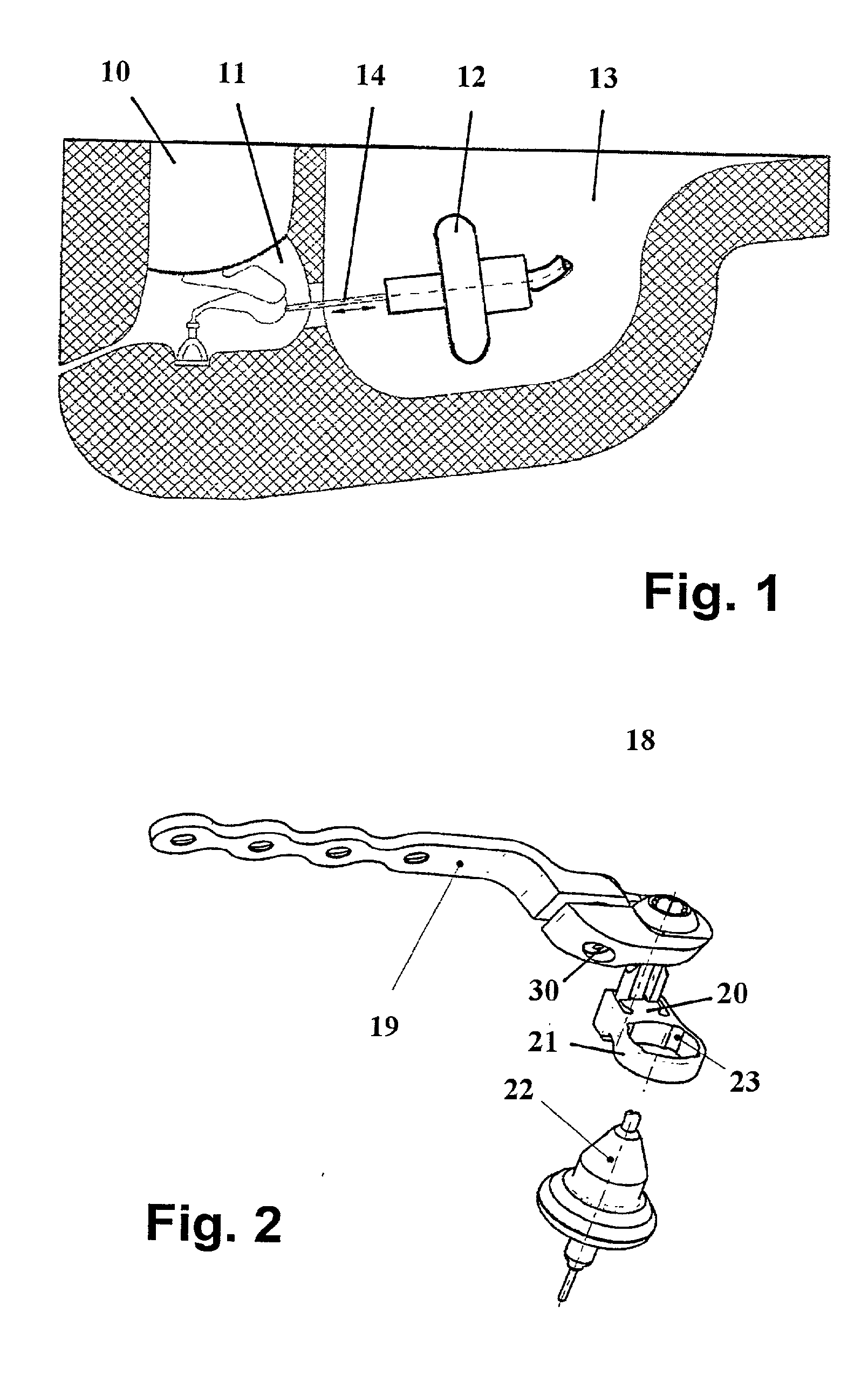
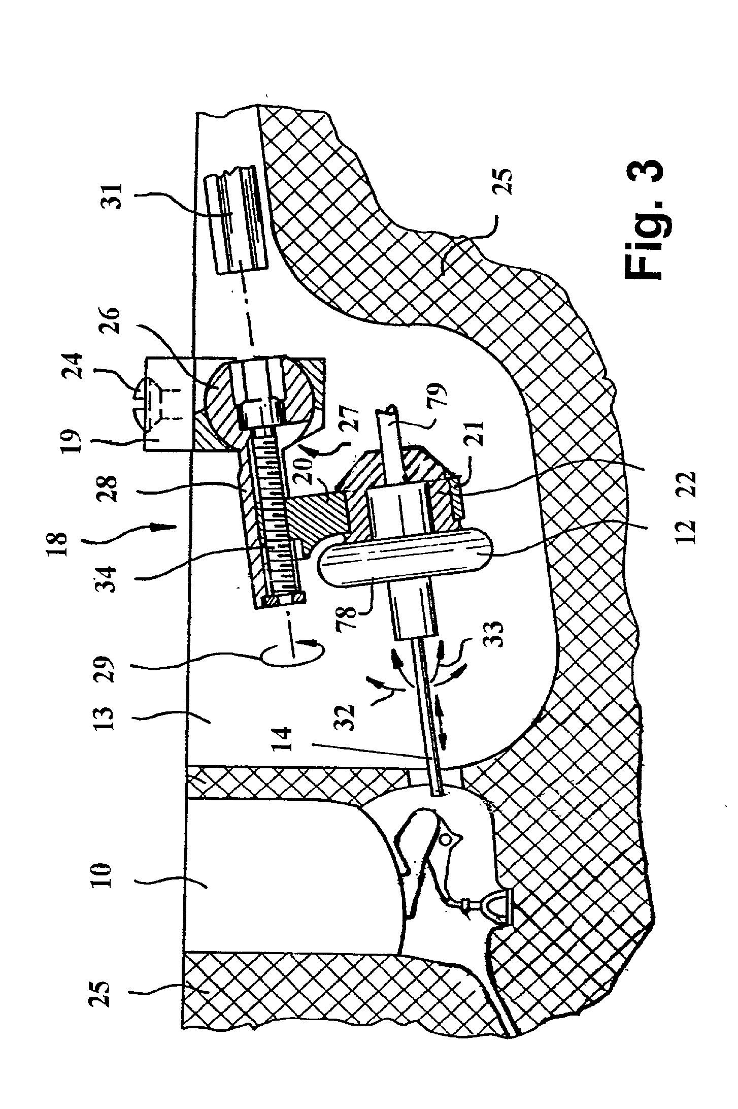
[0047]FIG. 1 shows a schematic sectional view of a human petrous bone including the external auditory canal 10, the middle ear 11 comprising the auditory ossicles malleus, incus and stapes (with the inner ear not being illustrated), and an electromechanical transducer 12 which is disposed in an artificial mastoid cavity 13. The transducer 12, in a manner known per se, is induced to mechanical vibrations, and in this embodiment the transducer 12 transmits such vibrations to the incus via a coupling rod 14 which extends through the natural access aditus ad antrum. The implantable positioning and fixing system (micromanipulator) is not illustrated in FIG. 1.

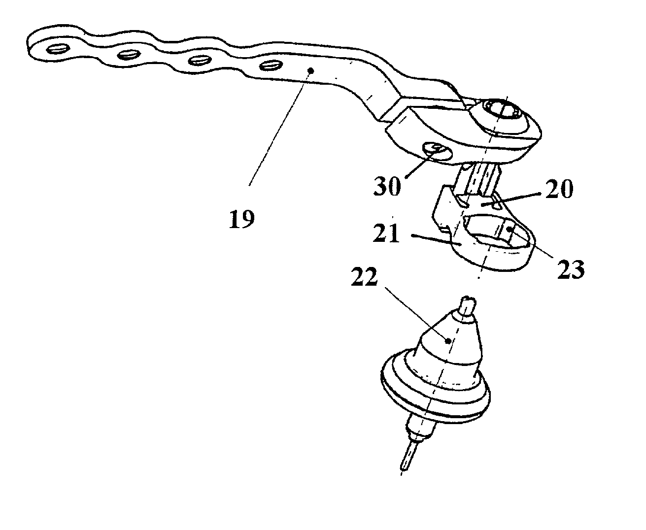
[0048]FIG. 2 shows an embodiment of an implantable micromanipulator 18 of the type described in detail in commonly owned U.S. patent application Ser. No. 09 / 468,853 which is hereby incorporated by reference. The micromanipulator 18 comprises an osteosynthesis plate 19 which is adapted to be fixed by screws to the cranial vault. Mic...


PUM


Abstract

An at least partially implantable hearing system comprising at least one electromechanical output transducer; a micromanipulator for positioning the transducer and for fixing the transducer in a position set by the micromanipulator, the micromanipulator being adapted to be fixedly attached by fixing means to a skull cap; and a releasable coupling unit disposed between the transducer and the micromanipulator, said coupling unit, in an assembled state, fixing the transducer with respect to the micromanipulator, and, in a released state, permitting removal of the transducer from the micromanipulator.

Description

CROSS-REFERENCE TO RELATED APPLICATIONS [0001] This application is a continuation of U.S. application Ser. No. 09 / 938,533, filed on Aug. 27, 2001, entitled, “At least Partially Implantable Hearing System,” which claims priority from German Application No. 100 47 388. 1, filed on Sep. 15, 2000. BACKGROUND OF THE INVENTION [0002] 1. FIELD OF THE INVENTION [0003] This invention relates to an at least partially implantable hearing system comprising at least one electromechanical output transducer and a micromanipulator for positioning the transducer and for fixing the transducer in a position set by the micromanipulator, the micromanipulator being adapted to be fixedly attached by fixing means to a cranial vault. [0004] 2. DESCRIPTION OF RELATED ART [0005] The expression “at least partially implantable hearing “system” is defined here as a system in which a sound signal is picked up by at least one sensor which transduces a sound signal into an electrical signal (microphone function), i...

Claims


Application Information

Patent Timeline
Patent Type & Authority Applications(United States)
IPC IPC(8): H04R25/00A61F2/18H04R25/02
CPCA61F2002/183H04R25/606H04R25/552
Inventor MULLER, GERD M.LEYSIEFFER, HANS
Owner COCHLEAR LIMITED
Why Eureka
Try Eureka