Safety needle syringe braking system

a safety syringe and syringe technology, applied in the field of safety syringe braking system, can solve the problems of additional training and cost, and mistakes may be made during the operation of safety syring

Inactive Publication Date: 2007-10-25
CREDENCE MEDSYST
View PDF3 Cites 12 Cited by
  • Summary
  • Abstract
  • Description
  • Claims
  • Application Information

AI Technical Summary

Benefits of technology

[0010] In a second embodiment of the retractable safety syringe, a second embodiment of the braking mechanism is provided. The second embodiment of the braking mechanism may comprise a base member and a friction member which are pivotable with respect to each other about a joint. The friction member has an up position and a down position. In the up position, an inner edge of a central aperture formed in the friction member frictionally engages a rigid shaft. Such frictional engagement produces a friction force which is greater than or equal to about the retraction force of the variable vacuum compartment. As the piston head is traversed between the retracted position and the extended position during operation of the safety syringe, the friction force of the friction member prevents traversal of the piston head toward the retracted position.

Problems solved by technology

Unfortunately, the additional training may be costly.
Also, since the operation of the safety syringe is not intuitive or fool proof, mistakes may be made during operation of the safety syringe.

Method used


Image

  • Safety needle syringe braking system
  • Safety needle syringe braking system
  • Safety needle syringe braking system

Examples


first embodiment

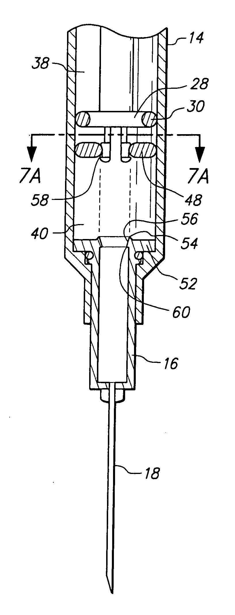
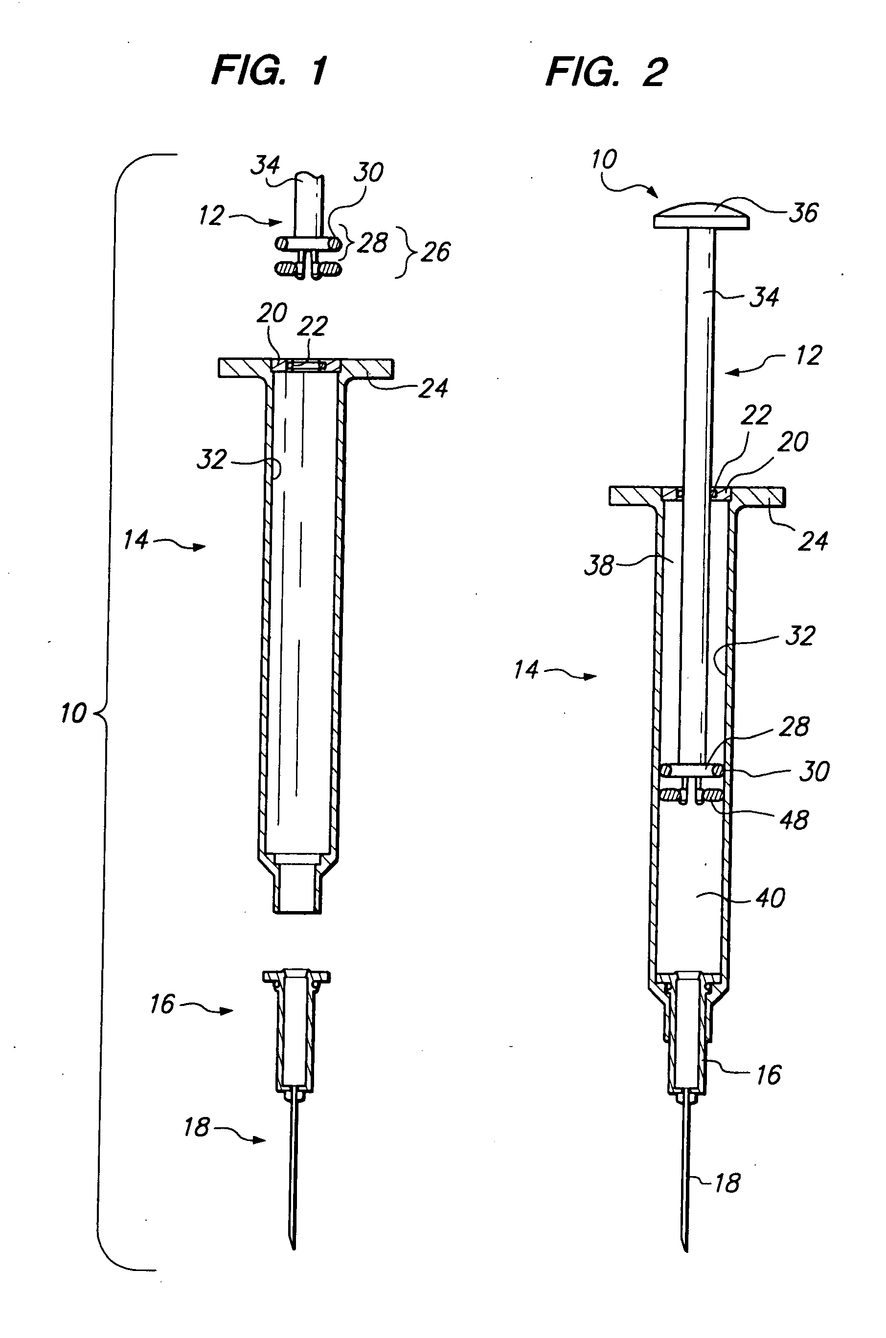
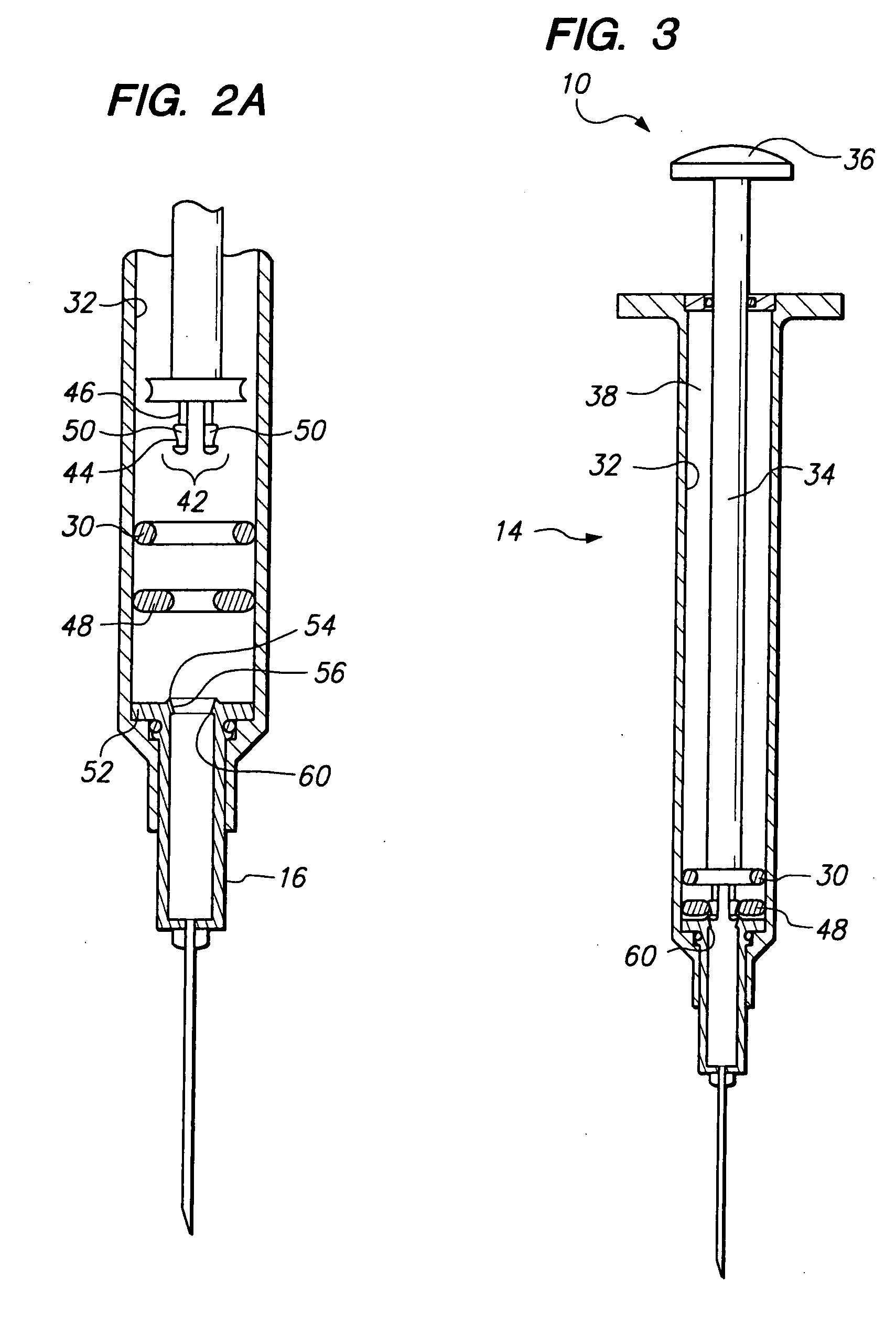
[0032] The thumb platform 36 and the finger platforms 24 work in conjunction with each other such that the user may depress the thumb platform 36 toward the finger platform 24 by pressing the thumb platform 36 with his / her thumb. This traverses the piston head 28 from a retracted position (see FIGS. 2 and 6) to an extended position or first extended position (see FIG. 3) or a fully extended position or second extended position (see FIG. 5). The piston head 28 may also be traversed from the extended position or first extended position to the retracted position by simultaneously pulling on the thumb platform 36 while pushing on the finger platforms 24. In relation to the safety syringe, generally, the retracted position is when the piston 26 is closer to the proximal end of the body 14 than the distal end of the body. But, the retracted position may include situations when the piston 26 does not contact the needle holder 16 and the piston 26 is closer to the distal end of the body 14 ...

second embodiment

[0047] In relation to the safety syringe, generally, the retracted position is when the piston 26 is closer to the proximal end of the body 14 compared to the distal end of the body 14. But, the retracted position may include situations when the piston 26 does not contact the needle holder 16 and the piston 26 is closer to the distal end of the body 14 compared to the proximal end of the body 14. Additionally, at the retracted position, the thumb platform 36 does not contact the friction member 102. The extended position or first extended position is when the piston 26 is closely adjacent to the needle holder 16 or in contact with the needle holder 16 and the piston 26 is not engaged to the needle holder 16. Additionally, at the extended position or first extended position, the thumb platform 36 may be closely adjacent to the friction member 102 or in contact with the friction member 102. Nonetheless, the pawl 110 is not engaged to the cam 112. The fully extended position or second ...


PUM


Abstract

A braking mechanism for a retractable safety syringe is disclosed herein. In a first embodiment, the braking mechanism is disposed about the distal end of a piston. The braking mechanism may comprise a friction material about a post attached to a piston. The friction material is displaced from a seat to a landing when the piston is traversed to a fully extended position to disengage the braking mechanism. In a second embodiment, the braking mechanism is disposed at a proximal end of a syringe body. The braking mechanism has a friction member which engages an outer surface of a rigid shaft of a plunger. The friction member is selectively pivotable to disengage the braking mechanism.

Description

CROSS-REFERENCE TO RELATED APPLICATIONS [0001] This application claims the benefits of U.S. Provisional Patent Application No. 60 / 788,796, filed Apr. 3, 2006.STATEMENT: FEDERALLY SPONSORED RESEARCH / DEVELOPEMENT [0002] Not Applicable BACKGROUND [0003] The present invention relates to a retractable safety syringe, and more particularly, to a braking mechanism to resist a retraction force during normal operation of the retractable safety syringe until a piston head engages a needle holder and needle to then withdraw the needle holder and needle within the safety syringe body. [0004] Retractable safety syringes are known in the art. For example, one type of retractable safety syringe is disclosed in U.S. Pat. No. 6,413,236 issued to Van Dyke, the entire contents of which are incorporated herein by reference. In the '236 patent, a retractable safety syringe has a piston which engages a needle holder and needle and retracts the same via a retraction force created by a variable vacuum comp...

Claims


Application Information

Patent Timeline
Patent Type & Authority Applications(United States)
IPC IPC(8): A61M5/32
CPCA61M5/3134A61M5/3234A61M5/346A61M2005/3104A61M5/3221A61M2005/31516A61M2005/3231A61M2005/3242A61M2005/3151A61M2005/323
Inventor OLIVER, RICHARD B.
Owner CREDENCE MEDSYST
Why Eureka
Try Eureka